1. Installation and adjustment of end switch
1.1 The installation should be as shown in Figure 1-1
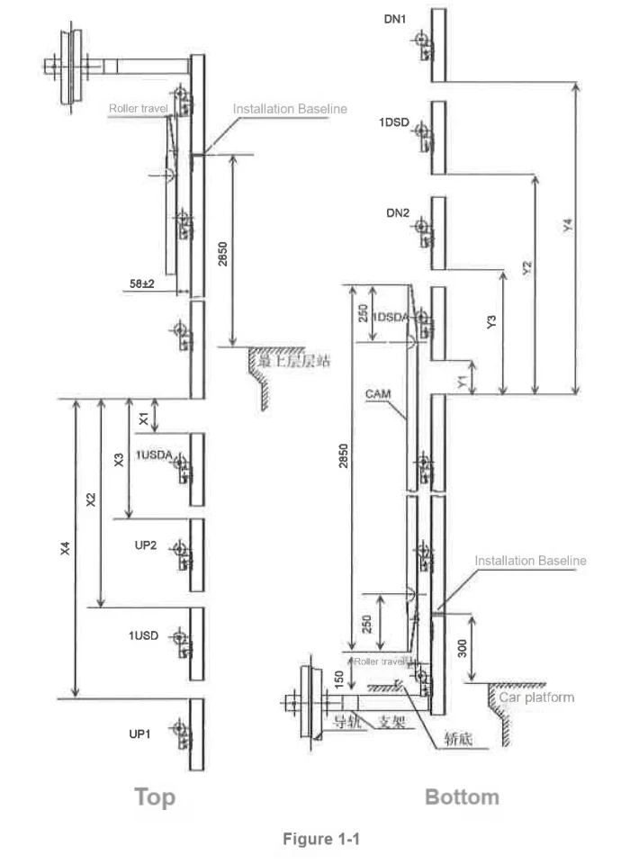
| Speed[m/sec] | Acceleration | SETS-L | X1(1USDA) | X2(1USD) | Y1(1DSDA) | Y2(1DSD) | X3(UP2) | X4(UP1) | Y3(DN2) | Y4(DN1) |
| 1 | StandArd | none | - | - | - | - | - | - | - | - |
| 1.6 1.75 | 1715 | 1765 | ||||||||
| 2.0 | 765 | 1515 | 815 | 1565 | ||||||
| High acceleration | have | 165 | 1965 | 215 | 2015 | |||||
| 1.6-2.0-2.5 1.75--2.0-2.5 2.0-2.5 2.5 | none | 2215 | 2265 | |||||||
| Standard | 1265 | 3615 | 1315 | 3665 | - | - | - | - | ||
| have | 1165 | 3515 | 1165 | 3515 | 1565 | 3965 | 1565 | 3965 | ||
| 3 | none | 1915 | 4265 | 1965 | 4315 | - | - | - | - | |
| have | 1415 | 3815 | 1465 | 3865 |
Installation Note:
a.The bracket should be installed so that it does not touch the switch device, guide rail bracket and connecting plate.
b.When using a sliding rail pressure plate, the distance between it and the bracket, rail bracket or rail fixing plate should be greater than 50mm.
c.Cover the open deep holes with pipe hole covers.
d.When using spring buffers, it is necessary to ensure that UOT and DOT have taken effect before the counterweight or car hits the buffer.
1.2 End switch device
1)Installation
The end switch data is as follows:
| Speed[m/sec] | Each switch action position [mm] (operation error range ±15mm) | |||||||
| UOT | DOT | UL/DL | USRA/DSRA *1 | USRB/DSRB | USR/DSR | 1USDA/1DSRA | 1USR/1DSR | |
| 1.0 | -200 | -200 | - | 270 | - | 1450 | - | - |
| 1.5 | 1250 | 2600 | ||||||
| 1.6 1.75 | 3400 | |||||||
| 1.6-2.0-2.5 *3 1.75--2.0-2.5 *3 | 1900 | 4050(3550) *2 | 6400(5000) *2 | |||||
| 2.0 | 3550 | 4300 | ||||||
| 2.5 2.0-2.5 *3 | 4050(3550) *2 | 6400(5000) *2 | ||||||
| 3 | 1900 | 2350 | 4700 | 7050 | ||||
*1 Option (when the door opening mode is 1D-1G or 2D2G and the terminal floor height is low)
*2 Applied to high acceleration elevators.
*3 Applied to variable speed elevators.
Note: When the elevator speed is 1.6, 1.75m/s, install two sets of terminal stop switches on the top and bottom floors.
When the elevator speed is 2.0, 2.5, 3.0m/s, install three sets of terminal stop switches on the top and bottom floors.
2) Debugging
In manual mode, move the car to the final floor leveling position at a speed of 20m/min. Set the car moving speed to 4m/min (SET1/0=0/4 A mode), and the car can move to the UOT/DOT switch contact position. In order to accurately measure the position, the car speed should be set to 4m/min on the previous floor, and then the car should be moved and passed the final floor. After the collision bow contacts the final switch, the debugging results are displayed by setting MON1=3 and MON=A or B.
① UOT Detection
When UL is canceled, the elevator goes up until the #29 light goes out, and the elevator stops at the position where UOT has been triggered.
Please make sure that the elevator does not stop because the car or counterweight is interfered with by other parts in the shaft.
② DOT Detection
When DL is canceled, the elevator goes down until the #29 light goes out, and the elevator stops at the position where DOT has been triggered.
Please make sure that the elevator does not stop because the car or counterweight is interfered with by other parts in the shaft.
Note: Since the UL/DL switch has been cancelled, there is no need to short-circuit any switch during the debugging process!
3) Special Features
① Virtual UL/DL functions
Since the UL/DL switch has been cancelled, a virtual UL/DL function has been added to the software to prevent UOT/DOT from being accidentally triggered during manual operation.
(1) During manual operation (on the car top or control panel), when the car passes the virtual UL/DL position, the virtual UL/DL function is triggered and the car stops automatically.
(2) When the car automatically stops at the virtual UL/DL position, the buzzer sounds.
(3) In the case where the virtual UL/DL function is triggered, when the USR switch is triggered, the car cannot move upwards. If the car moves downwards and the USR switch leaves the trigger position, the car can move upwards again. Similarly, when the DSR switch is triggered, the car cannot move downwards. If the car moves upwards and the DSR switch leaves the trigger position, the car can move downwards again.
(The position of the virtual UL/DL is measured with reference to the distance of USR/DSR)
(4) The virtual UL/DL function is disabled during and after the FMS function is started.
In addition, after the FMS function is started, the virtual UL/DL function can be changed from disabled to normal operation by setting the function (B mode SET1/0=7/E).
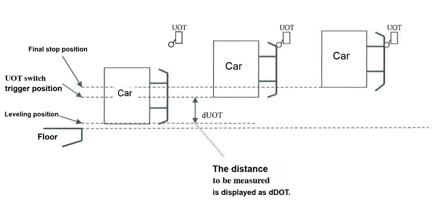
② UOT/DOT position measurement function
The UOFT/DOT position can be detected by the following steps:
Method for measuring UOT (the ones in brackets are for measuring DOT)
(1) Stop the car at the top [bottom] floor in automatic mode
(2) Check whether the leveling position error is less than 5mm (unless the car leveling position is correct, it is impossible to measure accurately)
(3) Set the rotary switch of P1 board (control cabinet) to SET1=0, SET0=0, and press SW1 (set to B mode)
(4) Set the rotary switch of P1 board to SET1=0, SET0=A[B], and press SW1.
(5) Set to manual mode and move the car upward [downward].
(6) The car moves upward [downward] at 4m/min, and stops when the UOT[DOT] switch is activated.
(7) The error of the UOT[DOT] position will be displayed on the seven-segment digital tube on the P1 board. *1
(8) After the measurement, the car is reset by the ED switch or short-circuiting the safety circuit (shorting the 75-77 signal on the R1 board). *2
(9) Set the rotary switch on the P1 board to SET1=0, SET0=8, and press SW1.
*1 The final stop position of the car is not measured, but the position when the UOT[DOT] switch is triggered.
*2 The safety circuit on the R1 board needs to be short-circuited only when the elevator does not have an ED switch device.
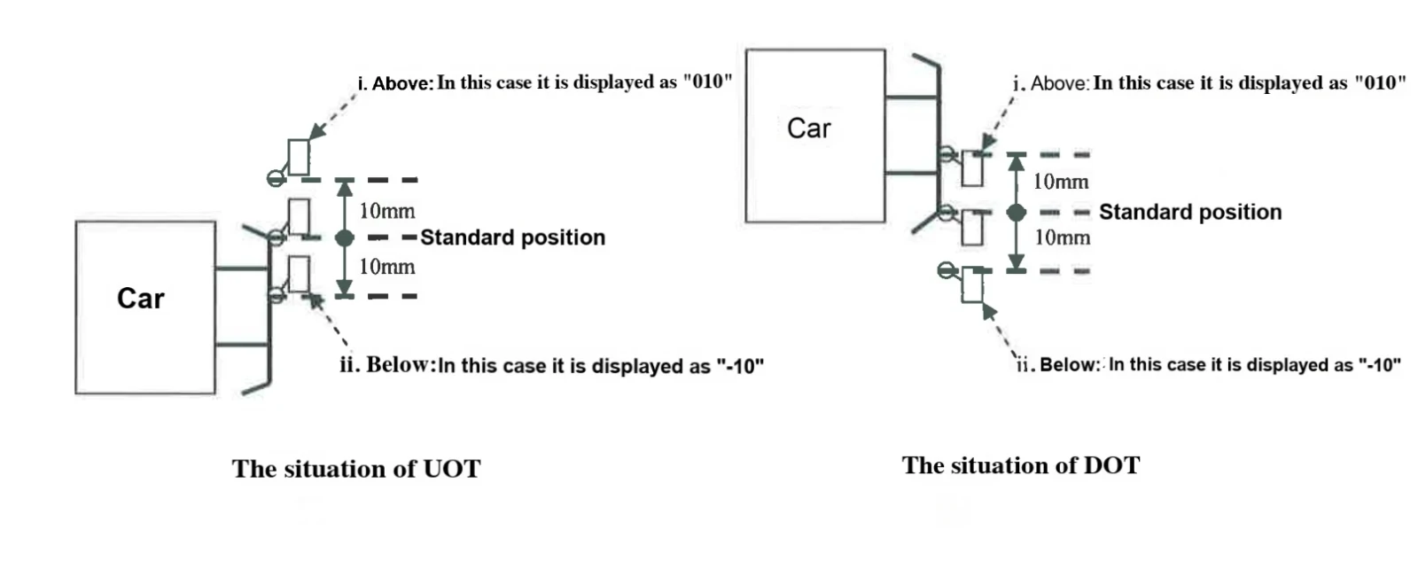
[How is the 7-segment digital tube displayed]
When the error is 10 mm (which means the switch position is above the standard position), the display is「010」.
When the error is -10 mm (which means the switch position is below the standard position), the display is「-10」.