A safety circuit can appear complicated because its contacts are spread across the car, hoistway, pit, and machine room. The useful starting point is the series path: each required contact must be in its permitted state before the safety relay can provide its signal to the controller.
This article explains the regenerative Mitsubishi Lingyun 2 arrangement described in the supplied Chinese training note, using the supplied wiring image for comparison. It is an explanation of that example, not a manufacturer-issued wiring specification for every Mitsubishi installation. Optional devices, terminal assignments, and connector revisions must be checked against the drawing for the actual elevator.
1. The DC 125 V series path
The training note describes a nominal DC 125 V supply entering at terminal 79. It passes through the car and control-cabinet stop section, the W1 interface, the hoistway and pit section, and the machine-room section before reaching safety relay 89 and return 00.
The main sequence is 79 → stop section → W1-73 → W1-75 → hoistway/pit section → W1-77 → machine-room section → W1-78/78A → relay 89 → 00. The simplified SVG below shows section boundaries and signal logic; it does not reproduce every connector, optional branch, or separate door-lock circuit.
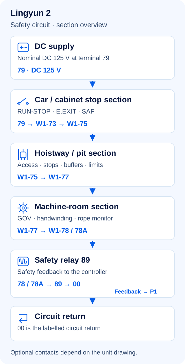
When the required series contacts are closed and the supply and relay circuit are healthy, relay 89 can energize. Its safety feedback is one condition for operation. A healthy safety chain alone does not establish that all other controller permissions are satisfied.
2. Car and cabinet stop section: 79 to W1-73
The first section combines maintenance stop contacts with car safety contacts. The note identifies the following five functions:
- Car operating-panel RUN-STOP. A maintenance stop control inside the car. The note describes two contacts in series on a two-entrance car; the onward wire to the car top is labelled SSE.
- Car-top RUN-STOP. Interrupts the safety chain for work on the car top. The example connects it between SSE and wire 71.
- Car emergency-exit contact, E.EXIT. Opening the car escape hatch opens this contact. The example places it between wires 71 and 72.
- Safety-gear contact, SAF. Reports operation of the safety gear. The contact interrupts the electrical chain; the mechanical safety gear provides the rail-gripping action. The example continues from wire 72 toward 73.
- Control-cabinet RUN-STOP. Completes this stop section before W1-73. The drawing calls it RUN-STOP; its exact relationship to an inspection or automatic selector depends on the installed controls.
The original image marks CG-JB03 on the car-side connection and WCG-PB03 at W1-73. These are drawing references for this example, not universal connector assignments.
3. Hoistway and pit section: W1-75 to W1-77
The second section covers access openings, pit stops, buffers, the governor-rope tension device, and terminal travel limits. An installation may have fewer contacts if optional access doors or devices are absent; the approved drawing determines its wiring.
- Landing emergency-exit door contact. Where such an access door is fitted, its contact confirms the permitted closed condition. This is distinct from the normal landing-door lock chain.
- Pit access-door contact. Monitors a separate pit entrance, where fitted. An open access door interrupts this section.
- Pit RUN-STOP. Provides a stop function for pit maintenance. Some arrangements have multiple series stop contacts; the supplied image includes optional second pit-stop devices.
- Counterweight buffer contact, PSF in the note. Monitors the counterweight-side buffer condition where a buffer switch is provided.
- Car buffer contact, PSE in the note. Monitors the car-side buffer condition. The scan identifies separate PSE and PSF hydraulic-buffer return contacts; match their operating conditions to the unit drawing.
- Governor-rope tension or break contact, GOV-T. Monitors the governor-rope tension arrangement in the pit. The note mixes rope-break and overspeed descriptions; this contact should not be treated as interchangeable with the machine-room overspeed-governor contact.
- Lower overtravel contact, DOT. Opens the illustrated safety path at the lower terminal condition. The example shows wire 76 between the lower and upper contacts.
- Upper overtravel contact, UOT. Opens the path at the upper terminal condition and continues toward W1-77. Confirm its final-limit function and operating position from the installed design.
The scan marks the W1-75 connection as WCH-PB05 and W1-77 as WCH-PB03, while the PDF prose uses the prefix WDH. Do not silently substitute one prefix for the other; compare the revision-matched drawing and physical connector markings.
4. Machine-room section: W1-77 to W1-78
- Car overspeed-governor contact, GOV. Interrupts the chain when the governor’s electrical trip mechanism operates. The governor also has a mechanical role in the safety system.
- Counterweight governor contact, CWT-GOV. An additional contact where a counterweight governor is installed. The original drawing explicitly shows alternatives with and without this device.
- Handwinding interlock. Prevents powered operation when the handwinding arrangement is not in its permitted condition. The note describes a cover-operated version; the installed mechanism determines the actual actuation.
- Slack-rope or rope-break contact. Included where the installation has that monitoring device. The drawing shows configuration alternatives, so its presence and identification require confirmation.
In the supplied image, the entry toward the governor includes WPK-PA05 / KB-JB02. The return toward W1-78 is marked KB-JA02 / WPK-PA03, while the PDF prose repeats WPK-PA05 for that return. This discrepancy cannot be resolved from the prose alone. Use the revision-matched unit drawing and physical connector labels.
5. What W1 voltage observations can tell you
The training note uses W1-73, W1-77, and W1-78 to narrow the suspected section. The table below explains those observations, assuming the stated supply is healthy, the section layout matches, and all observations use the verified circuit reference. It is a fault-location guide, not a live-testing procedure.
| Observation | Area to investigate | What remains unproven |
|---|---|---|
| No expected voltage at W1-73 | Supply to terminal 79, car/cabinet stop contacts, upstream wiring and connectors. | This does not identify a particular switch or exclude a supply fault. |
| Expected voltage at W1-73, absent at W1-77 | The W1-73-to-75 connection and the hoistway/pit section from 75 to 77. | The note groups this as a shaft fault, but the interconnection must also be considered. |
| Expected voltage at W1-77, absent at W1-78 | Machine-room contacts and the wiring/connectors leading to the return boundary. | It does not distinguish an operated device from poor contact or an open conductor. |
| Expected voltage at W1-78, but P1 safety indication is absent | The downstream 78/78A path, relay 89 circuit, return 00, relay feedback, and controller input. | A terminal voltage alone does not prove coil voltage under load or prove that the relay or P1 board is defective. |
The PDF’s last conclusion is too definite: voltage at 78 with no P1 indication is a reason to examine the downstream relay and feedback path, not sufficient evidence to replace a board. Record which state and section the observations support before assigning a component fault.
Electrical testing belongs to qualified personnel using the applicable manufacturer and site procedures. See OSHA’s electrical test-equipment requirements for a U.S. reference. Do not bridge safety contacts to restore passenger operation. Maintenance work requires the installation’s isolation, access-control, and return-to-service procedures.
6. Reading the supplied board photographs
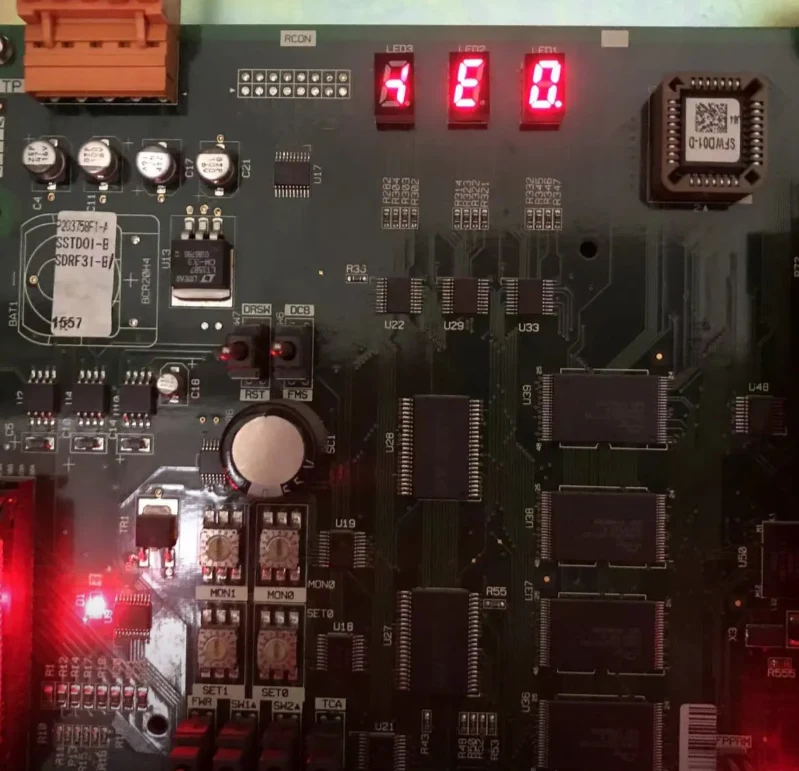
The training note refers to the P1 safety indication. The first board photograph illustrates why identification matters: display characters, selector positions, and LEDs belong to a specific board and operating context. The photograph alone does not identify the safety feedback state or justify interpreting the visible display as a particular fault code.
Before identifying a replacement board, match the full board number, revision, connector arrangement, and the wiring diagram. A similar outline or a shared Mitsubishi brand is not enough to establish interchangeability.
7. Drawing references and source notes
The scan includes a door-interlock branch labelled DS-B and relay/contact references around 89. These are not all reproduced in the overview SVG. Do not use the simplified main-chain diagram to conclude that door-lock monitoring is absent.
Source basis: the supplied 12-page Chinese training note, “Introduction to Mitsubishi Elevator Safety Circuits: Lingyun 2 Example,” and three supplied images. The note’s final page invites corrections, so its terminology and component-fault conclusions are treated as training commentary. All voltage values and numbered connections in this article describe that example; the installation’s approved manufacturer documentation remains the authority for service work.