一、Symptom & Root Cause
-
Symptom: "BKS" displayed on hall panel, elevator locked, typically triggered during automatic self-check after 30 mins of inactivity.
-
Root Cause:
-
Insufficient static brake torque (Threshold: ≥180N·m).
-
Unilateral brake failure (mechanical jamming or electrical fault).
-
二、Step-by-Step Troubleshooting
2.1 Static Torque Test Mode
Step 1: PrepAration
-
Safety Precautions:
-
Cut off main power, hang "Maintenance Mode" sign.
-
Move the elevator to top landing zone with no load, ensure car is stationary.
-
-
Tools Required:
-
LHS-420X control board, HIP hand-held terminal (connected to COP port).
-
Step 2: Enable Test Mode
-
Operate LHS-420X board:
-
Rotary switches:
SET1=0,SET0=1. -
Toggle
SW1△/▽to ▽ side (downward arrow).
-
-
Reboot System: Briefly press CP (Control Power) switch.
Step 3: Low-speed Upward Test
-
Switch to low-speed mode (via car top or control panel).
-
Press
RUNon HIP terminal to maintain low-speed upward movement.-
Key Note: Brake remains closed, system gradually increases torque.
-
Step 4: Torque Validation
-
Monitor hall display:
-
Normal: Numerical value ≥180 (Unit: N·m).
-
Abnormal: If <180, stop test immediately and proceed to unilateral brake test.
-
2.2 Unilateral Brake Test
Step 1: Exit Static Torque Mode
-
LHS-420X settings:
-
SET1=0,SET0=8, keepSW1▽downward.
-
Step 2: Enable Unilateral Control
-
Set LHS-420X monitor switches:
-
MON1=0,MON0=3.
-
Step 3: Manual Brake Release
-
Release Brake 1:
-
Press
RUN + UPon HIP terminal, hall display shows "B". -
Judgment: Car speed ≤2m/min is normal; "E" indicates failure.
-
-
Release Brake 2:
-
Press
RUN + DN, repeat the above process.
-
Step 4: Fault Handling
-
If "E" Displayed:
-
Stop operation immediately, cut off power.
-
Remove brake cover and check:
-
Brake spring alignment with marked line.
-
Brake surface contamination (clean with ethanol).
-
Lining thickness ≥2/3 of original.
-
-
三、Safety
-
Safety Warnings (Red/Bold):
🔴 NEVER adjust brakes without cutting main power!
🔴 Unilateral test requires two technicians: one operates HIP, another monitors the car.
四、Appendix
Figure 1: LHS-420X Switch Layout
| Switches | Function | Position |
|---|---|---|
| SET0/SET1 | Mode Select | Top-Left |
| MON0/MON1 | Monitor Mode | Right Side |
Figure 2: HIP Terminal Buttons
| Button | Function |
|---|---|
| RUN | Start/Stop |
| UP/DN | Direction Control |
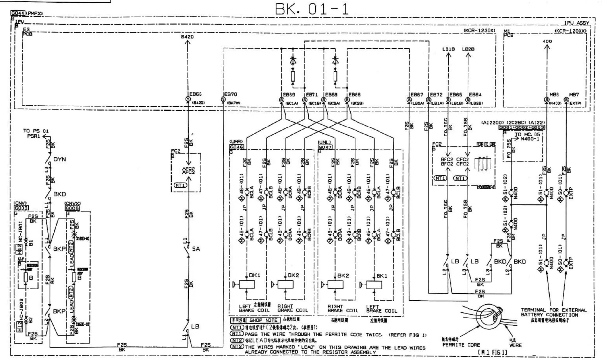
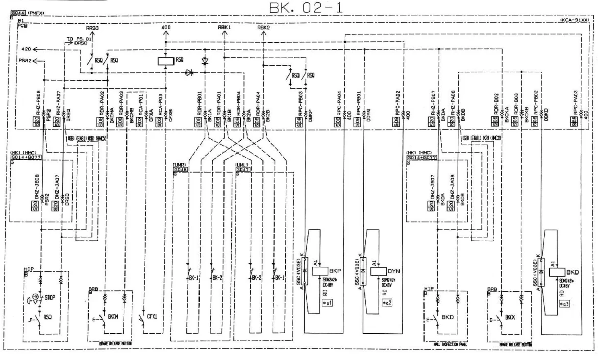
Figure 3: BK electrical drawings