
1. PrepAration before high-speed operation
1.1 Inspection of Rotary Switch Settings on Printed Boards
Ensure that the rotary switches on the human-machine interaction device are set to the specified settings during debugging.
| Table 1 Instructions for rotary switch | ||
| Name | Set value | Explain |
| MON1 | 1 | Display the current fault code of the elevator |
| MON0 | 0 | |
| SET1 | 0 | Avoid entering SET mode due to misoperation |
| SET0 | 8 | |
1.2 High speed operation series test
①. Move the normal/emergency electric and normal/maintenance switches in the control cabinet and car roof to the normal side.
The 60 LED on the human-computer interaction device will light up.
The 60 LED on the human-computer interaction device will turn off in abnormal mode.
②. The corresponding button on the control box inside the car will light up when this button is pressed.
1.3 High speed trial operation
①. Confirm that the elevator car door and landing door are fully closed (the 41 LED on the human-machine interaction device lights up);
②. Confirm that the DRSW/IND toggle switch on the human-machine interaction device is on the DRSW side to cut off the door machine;
③. Turn the automatic/emergency electric switch on the control cabinet to the automatic side, and the 60 LED on the human-machine interaction device should light up;
④. Confirm that SET1/0 is in the 0/8 position;
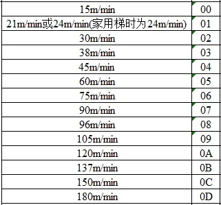
⑤. Press the SW1 switch on the human-computer interaction device to the upper or lower position, register the up or down command, and let the elevator automatically run up or down at high speed. The elevator running speed should not exceed the rated speed, and the rated speed corresponding to the speed code is shown in Table 2;
⑥. Confirm that there is no malfunction in the elevator and that the traction machine has no abnormal noise or vibration.
Table 2 Rated speed corresponding to speed code
2. Debugging for high-speed operation
High speed operation debugging must be carried out after confirming normal high-speed operation.
High speed operation debugging needs to be carried out in the order of adjusting the weighing device, no-load writing, balance coefficient adjustment (weight adjustment), half load writing, unilateral braking torque confirmation, automatic forced writing layer (with PAD), well switch position learning (with PAD), reference position learning (with well information system), balance coefficient and friction learning, ride comfort adjustment, leveling accuracy adjustment, TSD operation testing, braking torque confirmation, and load fluctuation inspection.
Please proceed with the following items in order!
2.1 Weighing adjustment (empty load)
2.1.1 Adjustment of Weighing Load Gauge
The weighing load meter is equipped with a single-chip computer that converts the load signal into a 0-5V linear voltage signal, which is used to adjust the starting torque of elevator equipment or for weight detection and control.
The specifications are as follows:
Input pressure: strain gauge bridge.
Power supply: -12V, 0,+12V.
Output signal: 0-5V linear voltage signal output.
Wiring method:
The 1st, 2nd, and 3rd pins of the weighing load meter are respectively connected to -12V, 0V, and+12V power supplies; 4. 5-pin output voltage signal.
Connect the 4-core plug of the sensor specific shielded cable to the socket of the weighing load gauge.
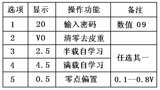
Debugging method: as shown in Table 3
①. In any state, press the 'Return' switch to immediately return the weighing load gauge to the measurement state.
②. Press the 'Settings' switch, and the instrument will make a sound every 2.5 seconds. At the same time, the first digit on the far left will display 1, 2, 3, 4, and 5 (representing options) in sequence and cycle. The second digit on the right will display the corresponding content according to Figure 5-1. When the' Settings' switch is released for a certain option, the instrument will no longer continue to make sound and wait for the operation or modification of that item. (*1)
③. Enter password: Press the "Settings" switch. When the first digit on the left displays 1 (indicating selection in item 1), release the "Settings" switch. The instrument will display 20. Then continue to press the "Settings" switch, and the displayed value will decrease. After adjusting to the value of 09, press the "Return" switch. The red (password) indicator light will flash, indicating that any of the following operations can be performed.
④. Reset (remove tare weight): When there is no load in the car, press the "Settings" switch. When the first digit on the left displays 2 (indicating selection in item 2), release the "Settings" switch. Next, press the "Settings" switch 3 times, and the digits on the right side of the instrument will display 1, 2, and 3. After 5 seconds, the instrument will have 1 echo, and the reset operation will end. Then, the digital display shows 0.5V (which is the zero bias value input by the zero bias operation), and similarly, the corresponding analog output value is also 0.5V.
⑤. Half load self-learning: (* 2) Load half load weight in the car, press the "Settings" switch, select option 3, release the "Settings" switch, the instrument displays 2.5 (as a half load prompt), then press the "Settings" switch 3 times, the digital display on the right side of the instrument will sound 1, 2, 3, and there will be 1 echo after 2 seconds, indicating the end of self-learning. Then, the instrument displays 2.5V, and the corresponding output value is also 2.5V.
⑥. Full load self-learning: Load the full load weight in the elevator car, press the "Settings" switch, select option 4, and release the "Settings" switch. The instrument displays 4.5 (as a full load prompt). Next, press the "Settings" switch 3 times, and the digital display on the right side of the instrument will sound 1, 2, and 3. After 2 seconds, there will be 1 echo, indicating the end of self-learning. Then, the digital display shows 4.5V, and similarly, the analog output value is also 4.5V. (*3)
⑦. Zero bias (item 5): The zero bias is set at 0.5V at the factory. If you need to change it, follow the steps below. Press the 'Settings' switch and select option 5. Release the' Settings' switch and the instrument will display 0.5. Next, press the 'Settings' switch to increase the value and cycle within the range of 0.1-0.8. After adjusting to the desired zero bias value, press the' Return 'switch to end the operation.
⑧. Note 1: When the -12V working power supply is not connected properly, the instrument displays (- d) as a prompt.
⑨. Note 2: Method for checking output: When the "Settings" switch is continuously pressed and the instrument is powered on, the instrument alternately displays L and P, corresponding to outputs of 0V and 4.0V, respectively. When the "Settings" switch is released, the instrument returns to normal operation.
<Attention>
*1 The password light must flash after entering the password (09) to operate.
*2 Either half load self-learning or full load self-learning is sufficient.
*3 When conducting a half load or full load self-study test, if the weight inside the cabin is too low, the instrument will emit three sounds as a warning.
Table 3 Adjustment Options for Weighing Load Gauge
2.1.2 Empty Load Data Writing
| Table 4 Steps for Empty Load Data Writing | ||
| Serial number | Adjustment steps | Precautions |
| 1 | ①. Write the unloaded (0% load) weighing value into the load controller (1) Empty the load inside the car; (2) Drive the elevator car to the midpoint of the shaft; When stopping, a slow stop method (RUN+UP+DN simultaneously pressed) should be used to avoid the random direction of mechanical friction caused by emergency stop, which affects the accuracy and linearity of the weighing device (3) Please refer to section 6.2.1.1 for the debugging method of the weighing load meter. | Method to confirm that the elevator car stops at the midpoint of the shaft: Set the rotary switch MON1 on the human-machine interaction device to 3, MON0 to 9, and put the elevator into emergency electric operation mode. The emergency electric operation of the elevator indicates that the current position of the car is in the middle position when the display changes from 0 to -0 or -0 to 0. The distance represented by the number change 1 is 256mm. |
| 2 | ②. Write the unloaded (0% load) weighing value into the flash memory (1) Set the rotary switch SET1 on the human-computer interaction device to 0, SET0 to 2, and the seven segment code will flash to display A02; (2) Press down the SW1 switch on the human-computer interaction device, the seven segment code will flash quickly, and then the current scale value will be displayed; (3) Press and hold down the SW1 switch on the human-computer interaction device again (for at least 1.5 seconds) until the seven segment code starts flashing. If it stops flashing, it indicates the end of the write operation; (4) Restore the rotary switches SET1 and SET0 on the human-computer interaction device to 0 and 8, respectively; (5) Press and hold down the SW1 switch on the human-computer interaction device until the seven segment code starts flashing rapidly, then exit SET mode; (6) Set the rotary switch MON1 on the human-computer interaction device to 0, MON0 to A, and the seven segment code will display the empty scale value in FLASH. Confirm successful writing. | SET1/0=0/2 |
2.2 Adjustment of Balance Coefficient
①. Stop the elevator on the ground floor and load the car with a balanced load (evenly distributed in the middle of the car as much as possible).
②. Run the elevator to the top floor in high-speed automatic mode, and record the motor current when the elevator reaches the midpoint of the shaft.
③. Then, in high-speed automatic mode, let the elevator run to the ground floor and record the motor current near the midpoint of the shaft.
④. Adjust the weight of the counterweight so that the difference in motor current recorded during up and down movements is within ± 0.5A.
<Attention>
*1: If the elevator car has secondary decoration, the balance coefficient needs to be adjusted before and after decoration.
*2: MON1/0=3/D can view the motor current value when passing through the midpoint of the shaft
2.3 Weighing adjustment (half load)
| Table 5 Half load scale value writing steps | ||
| Serial number | Adjustment steps | Precautions |
| 1 | ①. Write the half load (50% load) weighing value into the load controller (1) Move in 50% load; (2) Drive the elevator car to the midpoint of the shaft; When stopping, a slow stop method (RUN+UP+DN simultaneously pressed) should be used to avoid the random direction of mechanical friction caused by emergency stop, which may affect the accuracy and linearity of the weighing device. (3) Please refer to section 2.1.1 for the debugging method of the weighing load meter. | Method to confirm that the elevator car stops at the midpoint of the shaft: Set the rotary switch MON1 on the human-machine interaction device to 3, MON0 to 9, and put the elevator into emergency electric operation mode. The emergency electric operation of the elevator indicates that the current position of the car is in the middle position when the display changes from 0 to -0 or -0 to 0. The distance represented by the number change 1 is 256mm. |
| 2 | ②. Write the weighing value of the balanced load (50% load) to the flash memory (1) Set the rotary switch SET1 on the human-computer interaction device to 0, SET0 to 3, and the seven segment code will flash to display A03; (2) Press down the SW1 switch on the human-computer interaction device, the seven segment code will flash quickly, and then the current scale value will be displayed; (3) Press and hold down the SW1 switch on the human-computer interaction device again (for at least 1.5 seconds) until the seven segment code starts flashing. If it stops flashing, it indicates the end of the write operation; (4) Restore the rotary switches SET1 and SET0 on the human-computer interaction device to 0 and 8, respectively; (5) Press and hold down the SW1 switch on the human-computer interaction device until the seven segment code starts flashing rapidly, then exit SET mode; ③. Set the rotary switch MON1 on the human-computer interaction device to 0, MON0 to B, and the seven segment code will display the half load scale value in FLASH. Confirm successful writing. | SET1/0=0/3 |
| 3 | ④. Adjust overload detection point (29W) (automatic mode and in any door area) (1) Load the elevator car into 110% load in fully automatic mode (evenly distributed as much as possible); (2) Open the elevator door and confirm that the overload buzzer continues to sound and the elevator remains open; (3) If there is no action, adjust WGHO until condition (2) is met. | SET1/0=1/1 |
<Note>After writing the no-load and half load scale values, indicate them on the nameplate for backup purposes (NLWT, BLWT)
2.4 Confirmation of unilateral static braking torque
①. Stop the empty elevator at the upper terminal level door area;
②. Turn the rotary switch SET1 on the human-computer interaction device to 4, SET0 to 2, and the seven segment code will flash to display A42;
③. Press down the SW1 switch on the human-computer interaction device, the seven segment code will flash quickly, and then b0 will be displayed;
④. Press and hold down the SW1 switch on the human-computer interaction device again (for at least 1.5 seconds) until the seven segment code starts flashing rapidly, and then the slow flashing will display b0;
⑤. Operate the manual button to move up or down, and the elevator will release one brake (up BK1 opens, down BK2 opens);
⑥. For the triple brake, turn the DRSW/IND switch on the human-machine interaction device to the DRSW side, operate the manual button up or down, and BK3 opens;
⑦. Confirm that the elevator has not moved;
⑧. Restore the rotary switches SET1 and SET0 on the human-computer interaction device to 0 and 8, respectively;
⑨. Press and hold down the SW1 switch on the human-computer interaction device until the seven segment code starts flashing rapidly, then exit SET mode.
2.5 Automatically force layer writing when configuring PAD
After the balance coefficient adjustment and weighing device adjustment are completed, an automatic forced layer writing must be performed!
When installing the well information system, there is no such operation.
①. In automatic mode, park the elevator car at the lower terminal level;
②. Confirm that the elevator car door is fully closed (the 41 LED on the human-machine interaction device lights up);
③. Turn the DRSW/IND toggle switch on the human-computer interaction device to the DRSW side to cut off the door machine;
④. Set the rotary switch SET1 on the human-computer interaction device to 0, SET0 to 7, and the seven segment code will flash to display A07;
⑤. Press and hold down the SW1 switch on the human-computer interaction device until the seven segment code starts flashing, after which F01 will be displayed;
⑥. Press and hold down the SW1 switch on the human-computer interaction device again until the seven segment code starts flashing rapidly, and then it will flash slowly to display F00;
⑦. The elevator will automatically run upwards at a speed of 60m/min (if the rated speed is less than 60m/min, then at the rated speed) to start writing floors;
⑧. The elevator stops when it reaches the upper terminal level. If the floor writing is successful, the seven segment code display will stop flashing;
⑨. Restore the rotary switches SET1 and SET0 on the human-computer interaction device to 0 and 8, respectively;
⑩. Press and hold down the SW1 switch on the human-computer interaction device until the seven segment code starts flashing rapidly, then exit SET mode.
<Attention>If unable to write layer height data, check the action position of the terminal limit switch, leveling/re leveling device, and encoder
2.6 When equipped with PAD, learn the position of the well switch
After the automatic layer writing is completed, it is necessary to perform a well switch position learning once!!!
When installing the well information system, there is no such operation.
①. In automatic mode, park the elevator car at the lower terminal level;
②. Turn the rotary switch SET1 on the human-computer interaction device to 8, SET0 to 1, and the seven segment code will flash to display A81;
③. Press and hold down the SW1 switch on the human-computer interaction device until the seven segment code starts flashing rapidly. After that, the TSD switch position deviation measured last time will be displayed (in cm, if there is no measured data, it will show ---);
④. Press and hold down the SW1 switch on the human-computer interaction device again until the seven segment code starts flashing rapidly, and then slowly flash to display dS4 (terminal switch and flat area);
⑤. Press the SW2 switch on the human-computer interaction device upwards to register the top floor command. The elevator will run upwards at a speed of 60 m/min (if the rated speed is less than 60 m/min, then at the rated speed) and start learning;
⑥. The elevator stops when it reaches the top floor, and the seven segment code displays the measured TSD switch position deviation in centimeters;
⑦. Press and hold down the SW1 switch on the human-computer interaction device again until the seven segment code starts flashing rapidly, and then slowly flash to display uS4 (terminal switch and flat area);
⑧. Press the SW2 switch on the human-computer interaction device downwards to register the ground floor command. The elevator will run downwards at a speed of 60 m/min (if the rated speed is less than 60 m/min, then at the rated speed) and start learning;
⑨. The elevator stops when it reaches the bottom floor, and the seven segment code displays the measured TSD switch position deviation in centimeters;
⑩. Confirm that the TSD switch position is installed correctly (a positive deviation indicates that the actual installation position of the TSD is higher than the theoretical position, and vice versa);
⑪. Restore the rotary switches SET1 and SET0 on the human-computer interaction device to 0 and 8, respectively;
⑫. Press and hold down the SW1 switch on the human-computer interaction device until the seven segment code starts flashing rapidly, then exit SET mode.
| Table 6 Meaning of Level Area | |
| Leveling Area | Meaning |
| 0 | Outside the Level Area |
| 1 | Upper level area |
| 2 | Door area |
| 3 | Upper further level area |
| 4 | Level target area |
| 5 | Lower further level area |
| 6 | Lower level area |
2.7 Reference position learning when equipped with a well information system
①. In automatic mode, when the elevator stops at the ground floor door area without direction standby, set SET1/0 to 5/8, press the SW1 switch down, and the seven segment code will display the synchronization layer;
②. Press and hold the SW1 switch down for at least 1.5 seconds until the seven segment code starts flashing;
③. Register the instruction to make the elevator run upwards. After the elevator stops, the seven segment code will display the distance between the reference switch and the ground floor level position, and stop flashing. It is necessary to confirm that the distance is within 50 ± 5 (mm);
④. If the reference position reading fails, it will display "Er1", and if the reference position is abnormal, it will display "Er2";
⑤. Set SET1/0 to 0/8, press down the SW1 switch to exit the reference position learning mode;
⑥. Reset the P1 board or power off the elevator before powering it back on.
2.8 Balance coefficient and friction learning
①. In automatic mode, park the car unloaded at the lower terminal level;
②. Set the rotary switch SET1 on the human-computer interaction device to 6, SET0 to D, and the seven segment code will flash to display A6D;
③. Press down the SW1 switch on the human-computer interaction device, and the seven segment code will flash quickly, displaying floor and status information;
④. Press and hold down the SW1 switch on the human-computer interaction device again (for at least 1.5 seconds) until the seven segment code starts flashing rapidly, and then it will flash slowly;
⑤. Press the SW2 switch on the human-computer interaction device upwards to register the top floor command. The elevator will run upwards at rated speed and begin measuring the current at the middle position of the up shaft;
⑥. When the elevator reaches the top floor, stop and press down the SW1 switch on the human-machine interaction device again (at least 1.5 seconds) until the seven segment code starts flashing rapidly;
⑦. Press the SW2 switch on the human-computer interaction device downwards to register the ground floor command. The elevator will run downwards at rated speed and start measuring the current in the middle position of the down shaft The elevator stops running to the ground floor, and the digital display on the human-machine interaction device should show the balance coefficient in%;
⑨. Confirm that the balance coefficient is between 45 and 50;
⑩. Set "SET1" to "0" and "SET0" to "8" on the human-computer interaction device, press and hold down the SW1 switch on the human-computer interaction device until the seven segment code starts flashing rapidly, and exit SET mode.
2.9 Comfort adjustment for passengers (generally not adjusted)
2.9.1 Fine adjustment of torque compensation (usually not adjusted)
①. When operating NL UP or NL DN without load, the car tends to move upwards when the brake is opened. Adjust WGHG to F;
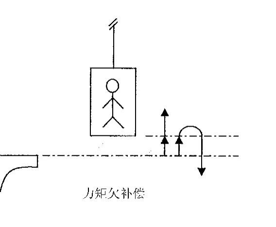
②. When operating NL UP or NL DN without load, the car tends to move downwards when the brake is opened. Adjust WGHG to 0.
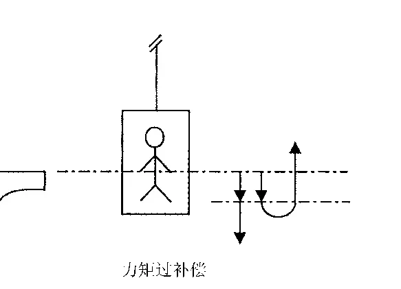
The following methods can render the torque compensation function ineffective:
Adjust WGHG to 0.
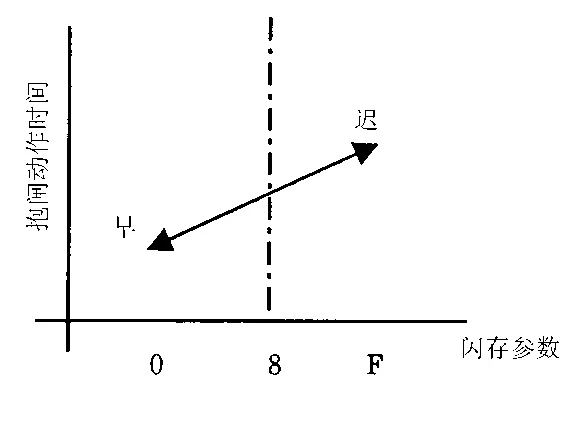
2.9.2 LTB (Delay Brake Time Adjustment during Stopping)
The stop vibration caused by premature release of the brake when the car stops can be solved by adjusting the LTB parameters. If the delay braking time is too short, adjust the parameter in the direction of F; If it is too long, adjust towards 0 direction(SET1/0=1/7).
2.10 Leveling accuracy adjustment
2.10.1 PTSH (Residual Distance Offset Parameter Adjustment)
If the elevator car exceeds the up and down stop positions on all floors (the up car is higher and the down car is lower), then increase this parameter (approximately 2mm/position), SET1/0=1/2; On the contrary, if the elevator car has "insufficient" up and down stop positions on all floors (the up car is too low and the down car is too high), then the parameter will be reduced.
2.10.2 DNSH (DZU Position Correction Parameter Adjustment)
If the elevator car "exceeds" the downward stop position on all floors (the car is low), then increase this parameter (approximately 2mm/position), SET1/0=1/3; On the contrary, if the elevator car has "insufficient" downward stop positions on all floors (the car is too high), then the parameter will be reduced.
2.10.3 WGCPN (Adjustment of Load Variation Compensation Parameters)
If the leveling accuracy of the elevator is normal when unloaded, but the leveling position of the car is low when fully loaded, then increase this parameter (1mm/position).
2.11 TSD Running Test
①. Place the elevator car in an unloaded state and stop within the door area of the basement;
②. Set the rotary switch SET1 on the human-computer interaction device to 0, SET0 to F, and the seven segment code will flash to display A0F;
③. Press down the SW1 switch on the human-computer interaction device, the seven segment code will start flashing, and then the floor information will be displayed;
④. Press and hold down the SW1 switch on the human-computer interaction device again (for at least 1.5 seconds) until the seven segment code starts flashing rapidly, and then the slow flashing will display the floor information Press the SW2 switch on the human-computer interaction device upwards to register the top floor command. After the car runs, it will stop at the top floor along the TSD graphic to confirm that the elevator leveling accuracy meets the requirements;
⑥. Press and hold down the SW1 switch on the human-computer interaction device again (for at least 1.5 seconds) until the seven segment code starts flashing rapidly, and then the slow flashing will display the floor information;
⑦. Press the SW2 switch on the human-computer interaction device downwards to register the ground floor command. After the car runs, it will stop at the ground floor along the TSD graphic to confirm that the elevator leveling accuracy meets the requirements;
⑧. After two TSD actions, the elevator will enter a state where it cannot be restarted and a reset operation is required;
⑨. Set the rotary switch SET1 to 0 and SET0 to 8 on the human-computer interaction device, press and hold the SW1 switch down until the seven segment code starts flashing rapidly, and exit the SET mode.
2.12 Confirmation of Braking Torque
2.12.1 Bilateral static braking torque measurement
①. Stop the elevator with no load at the upper terminal level door area and switch to emergency electric mode;
②. Set the rotary switch SET1 on the human-computer interaction device to 0, SET0 to 1, and the seven segment code will flash to display A01;
③. Press down the SW1 switch on the human-computer interaction device, the seven segment code will flash quickly, and then the last measured value will be displayed;
④. Press and hold down the SW1 switch on the human-computer interaction device again (for at least 1.5 seconds) until the seven segment code starts flashing rapidly, and then it will flash slowly;
⑤. Emergency electric upward movement, the motor brake does not release, but the applied torque continues to increase. When the motor starts to rotate or reaches its maximum torque, the measurement process ends, and the seven segment code will stop flashing, displaying the measured static torque;
⑥. If the measurement fails, it will display E. After troubleshooting, repeat [1]~[5];
⑦. Confirm that the measured static moment value meets the requirements. If it does not meet the requirements, corresponding measures need to be taken before retesting until the requirements are met;
⑧. Restore the rotary switches SET1 and SET0 on the human-computer interaction device to 0 and 8, respectively;
⑨. Press and hold down the SW1 switch on the human-computer interaction device until the seven segment code starts flashing rapidly, then exit SET mode.
2.12.2 Dynamic Braking Torque Measurement
①. Stop the elevator car to a non top door area, keep the car empty, and switch to emergency electric operation mode;
②. Set the rotary switch SET1 on the human-computer interaction device to 0, SET0 to B, and the seven segment code will flash to display A0b;
③. Press down the SW1 switch on the human-computer interaction device, the seven segment code will start flashing, and then the synchronization layer will be displayed;
④. Press and hold down the SW1 switch on the human-computer interaction device again (for at least 1.5 seconds) until the seven segment code starts flashing rapidly, after which the car speed (unit: m/min) will be displayed;
⑤. Emergency electric upward operation, with a running speed of min {45m/min, rated speed}. When the car reaches a distance of 450mm from the reference point of the top floor (when equipped with PAD, it will run to the USR switch action position), it will stop urgently;
⑥. The seven segment code will display the measured emergency stop distance in 2mm units;
⑦. If the measurement fails, the seven segment code will display E;
⑧. After the measurement is completed, set the rotary switch SET1 on the human-computer interaction device to 0, SET0 to 8, and press down the SW1 switch until the seven segment code starts flashing rapidly, then exit the SET mode.
2.13 Load variation inspection
Change the car load from 0% to 110% and confirm the following requirements.
①. The leveling error is within ± 5mm. If it does not meet the requirements, adjust the WGCPN parameters according to 6.2.10.3.
②. There is no significant change in ride comfort, especially near the door area.
③. The vibration amplitude and noise are within the range specified by the standard.
④. The current of the motor does not exceed the rated current value when it is running at full load.
3. High speed operation
3.1 High speed operation
①. Use low-speed mode to stop the elevator car near the middle position of the shaft.
②. Confirm that the switch "NORMAL/EMERGENCY" on the emergency electric operation device is turned to the "NORMAL" side, and at the same time, place the "NORMAL/INSPECTION" on the car roof station operation box in the normal "NORMAL" state, and turn all operation/stop switches to the running position.
③. Register a call for the floor closest to the stopping position of the elevator car. The elevator car should be level normally. After confirmation, summon each floor (once up/down) to confirm if the car leveling is good.
④. Perform automatic operation of crossing one floor and two floors in sequence, and confirm whether the car leveling is good.
3.2 Confirmation of Basic Functions for High Speed Automatic Operation
①. The debugger operates the elevator inside the car.
②. Press each command button inside the car, and all command buttons at other floors except this one should light up.
③. The elevator can accurately level at the floor where the instruction is registered, automatically open the door after leveling, and eliminate the instruction response light at that floor.
④. Step by step check the floor call button, and after the elevator leaves, the response light for each button can be turned on when pressed.
⑤. Elevators can respond to call signals in the same direction. At floors with call signals in the same direction, elevators can accurately level and eliminate the call response light signal. After leveling, the doors can automatically open.
⑥. Under the condition of no call or command ahead, the elevator can respond to reverse call signals. At this time, at the level where there is a reverse call, the elevator can accurately level the floor, and at the same time, the call response light signal can be eliminated, and the door can automatically open after leveling.
⑦. The door opening function on this floor is effective. When the elevator stops at a certain floor station and presses the up or down call button of the floor station, unless the elevator has already had the opposite direction of operation before, the elevator will open the door or change the closing action to the opening action.
⑧. Check the function of the light curtain safety touch panel. During the process of closing the elevator door, the light curtain safety touch panel installed at the edge of the car door will switch to the opening action when it touches the obstruction.
⑨. Confirm that the door opening and closing buttons inside the elevator car are effective.
⑩. Confirm that the floor display data inside the elevator and at the station is correct when the elevator is on any floor.
⑪. Overload test. Gradually increase the load inside the elevator car and confirm that when the load exceeds 110% of the rated load, the overload protection device of the elevator will activate, the overload buzzer will sound, and the car cannot be closed or started.


