
1. Controller connection status
Plug the network cable of the LCD controller into the PC and restart the controller. After the controller is started and successfully connected to the PC, log in to the host computer. In the "LCD Controller Management" interface, after adding the controller, all controller states should be listed. One controller state occupies one line. Check whether each state is correct. If it is connected, it will be displayed in green, otherwise it will be displayed in red, as shown in Figure 1-1. You can re-edit the name of the controller by directly clicking on the controller name. It is recommended that the name should be easy to identify the elevator corresponding to the controller.
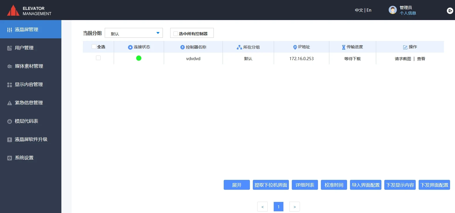
Figure 1-1 Connection between controller and PC
2. Floor code table and volume setting
Step ① Debug the floor display. Start the elevator, the LCD display device should be able to display the running direction and floor, the touch screen should be able to display all floors, the system defaults to displaying the standard floor name, if the elevator has non-standard, there may be no floor display. The specific setting method is: as shown in Figure 2-1, in the "Floor Code Table" interface, click the "Add" button. After entering the name of the floor code table, click the "OK" button. As shown in Figure 2-3, enter the floor name next to the display code, for example, enter "12A" in the text box corresponding to "7F". When used for the touch screen control box interface, enter the four-digit password in the corresponding place of the floor where the password needs to be set, and click the "Save" button after the setting is completed. As shown in Figure 2-4, select the newly added code table, click "Download to Controller", check the controller to which the floor code table needs to be issued in the pop-up dialog box, click the "Save" button to start downloading, and after the download is successful, the controller can correctly display the non-standard floor name at the corresponding floor.
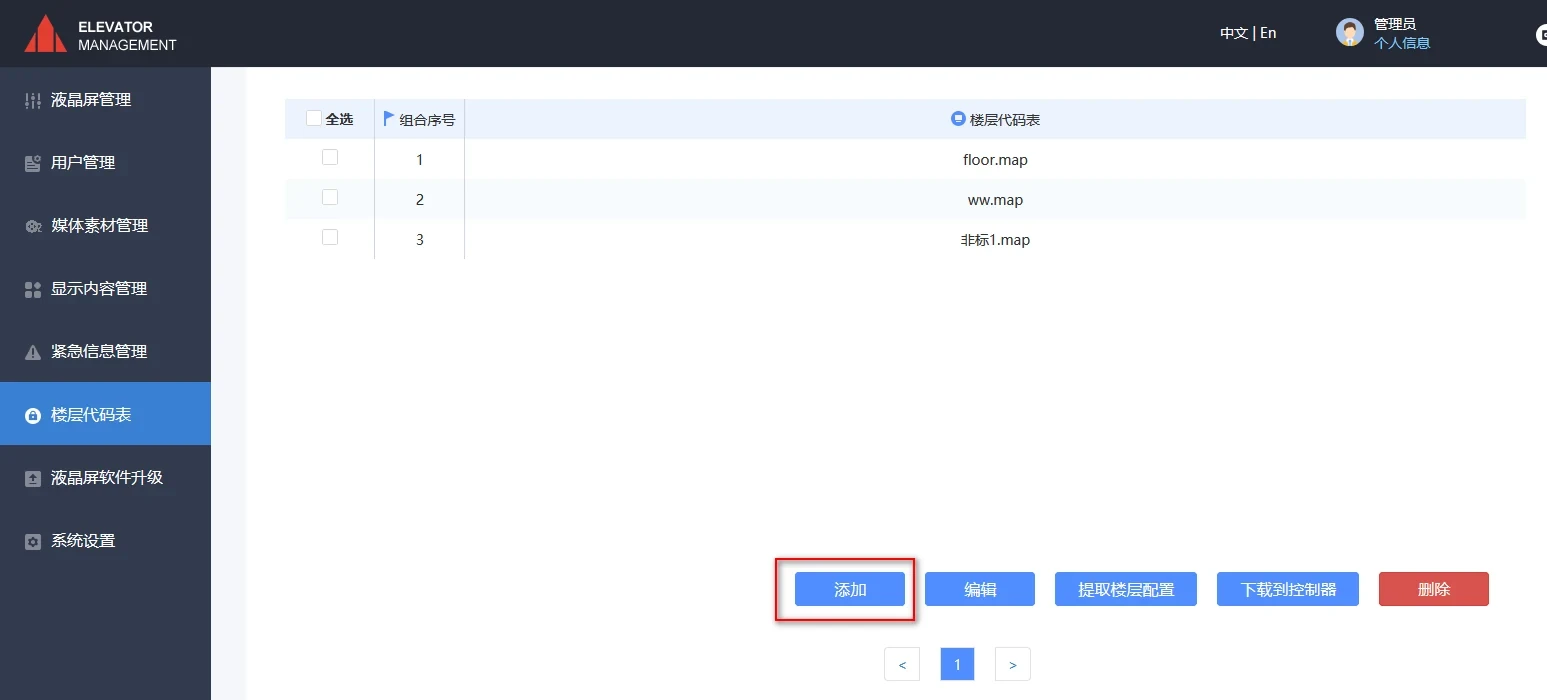
Figure 2-1 Adding floor code table
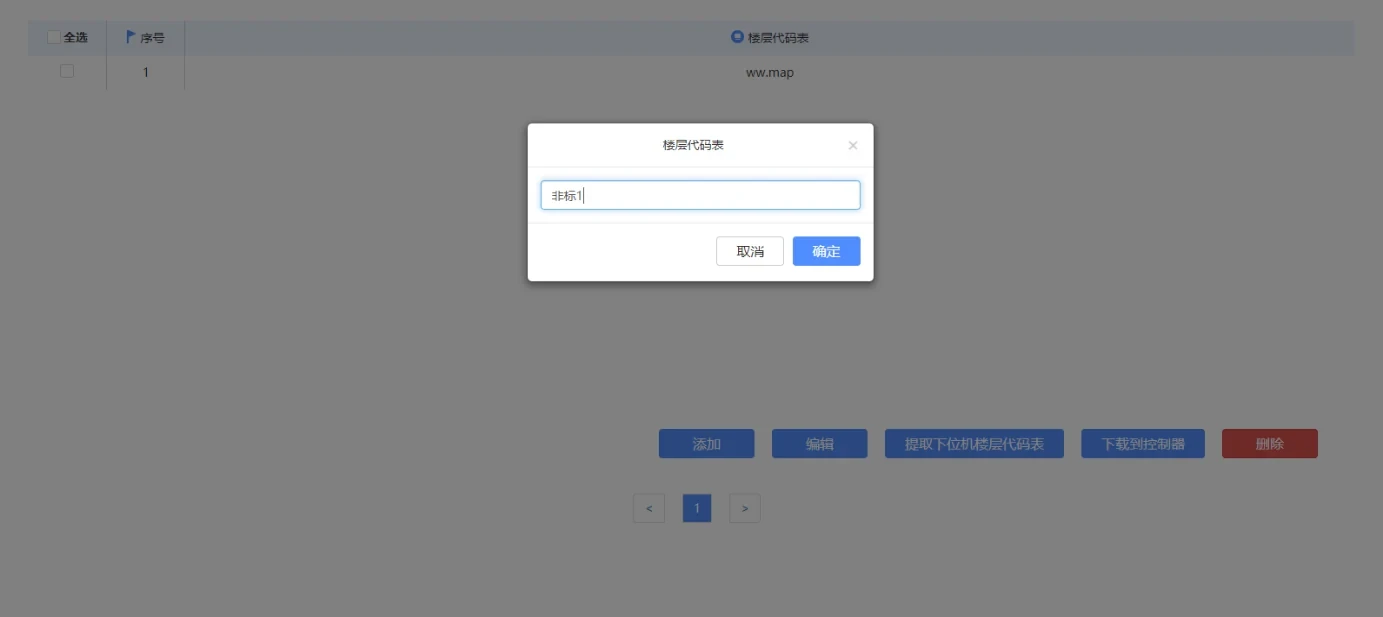
Figure 2-2 Enter the name of the floor code table
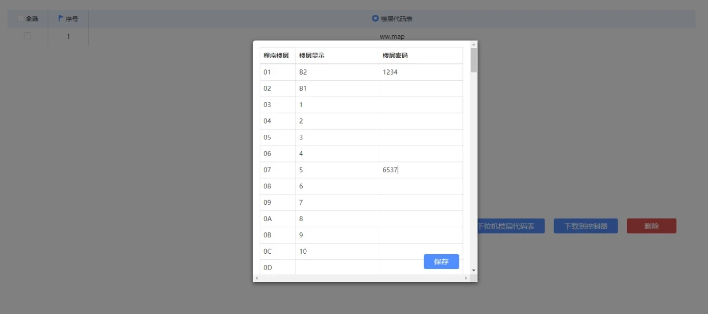
Figure 2-3 Setting floor name and password
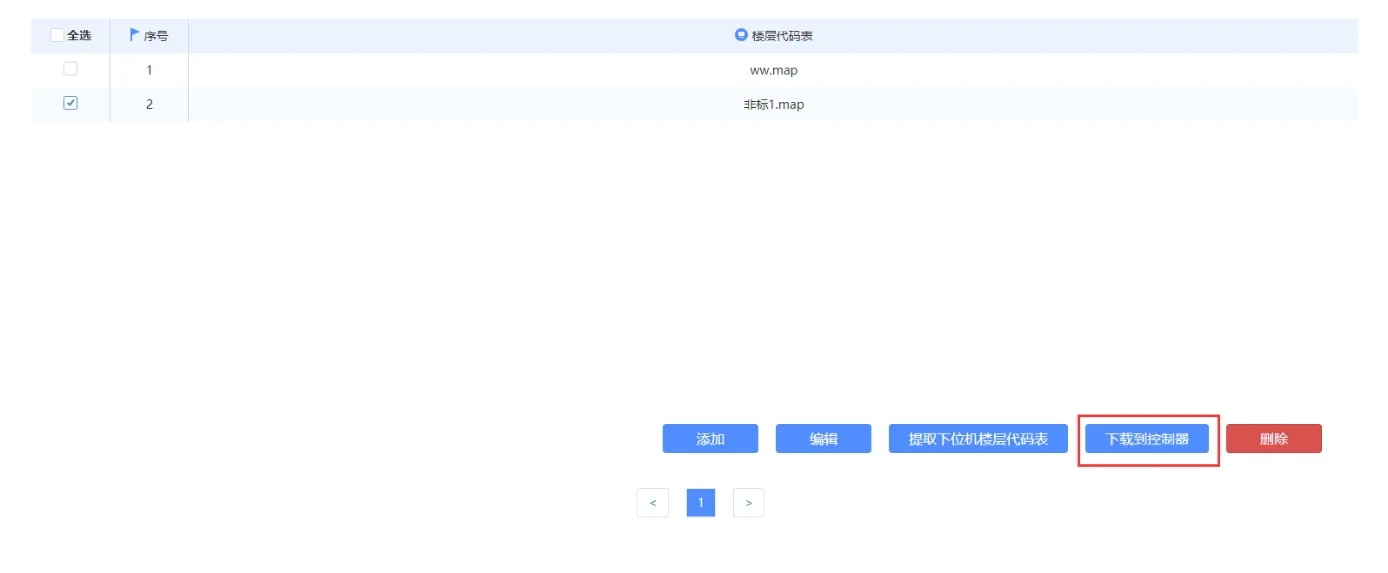
Figure 2-4 Downloading the floor code table to the controller
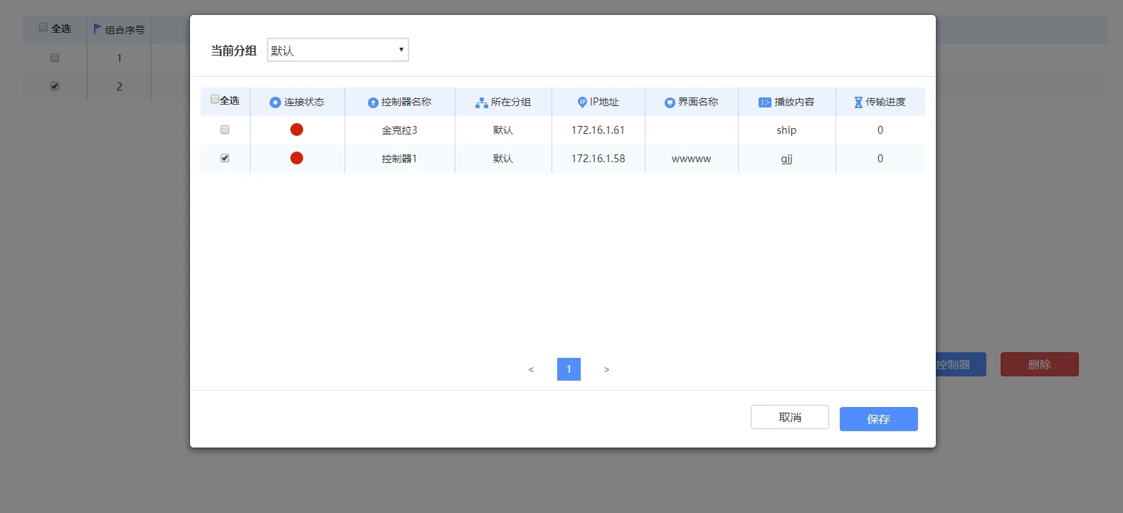
Figure 2-5 Select Controller
Step 2 Adjust the volume. In the “LCD Controller Management” interface, select the controller whose volume needs to be adjusted, click the “Set Volume” button, and adjust the volume to a moderate level, as shown in Figure 2-6.
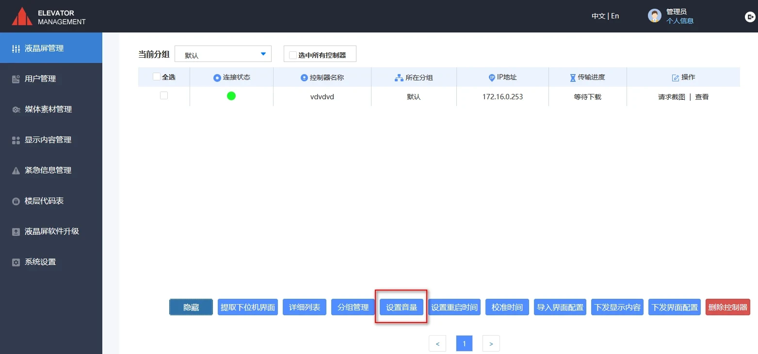
Figure 2-6 Adjusting the volume
3. Media material management
①. After entering the system, first upload multimedia materials (video, pictures, audio, subtitles, etc.). Click "Media Material Management" on the left column, and select the type of material to be uploaded in the drop-down menu. Here, take picture materials as an example: click the "Upload" button, then click "Browse" in the pop-up window, select the picture to be uploaded, click "Open", and click "Upload". The interface after uploading is as shown in Figure 3-1. For other upload steps such as video, audio and background materials, refer to the above example.
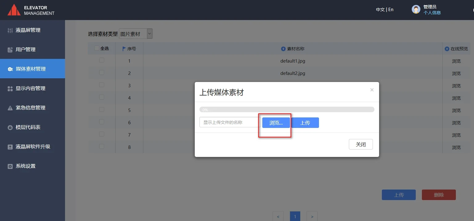
Figure 3-1 Open the upload window
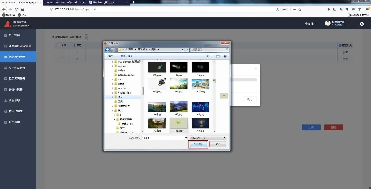
Figure 3-2 Select the material to be uploaded
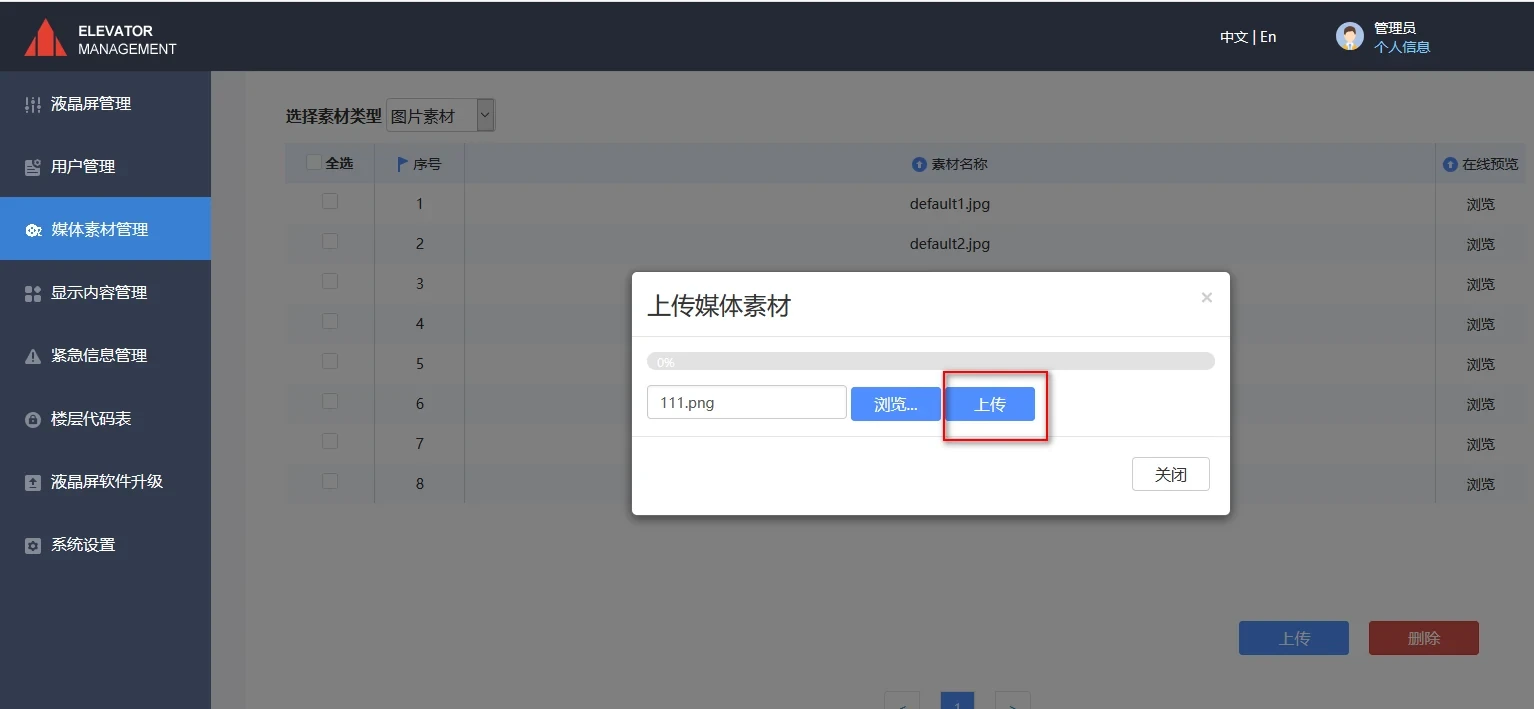
Figure 3-3 Upload selected material
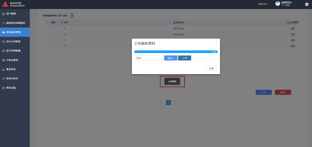
Figure 3-4 Upload completed
②. The supported material formats are as follows:
| Supported image formats: | jpg, png, gif |
| Supported video formats: | mp4, 3gp, avi, flv, mov, rmvb, wnv |
| Supported audio formats: | mp3, aac, ape, m4r, ogg, wav, wma |
4. Display content management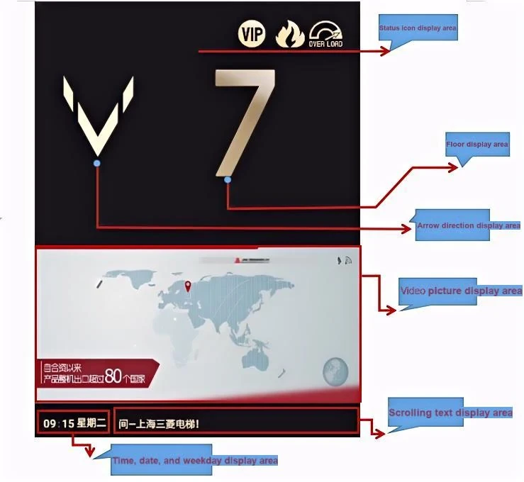
4-1 Interface Description
Select "Display Content Management" in the left column, then click the "Add" button, and the interface shown in Figure 4-2 will appear. First, name the added display content and type the "File Name" in the red box in Figure 4-4. Select the type of multimedia to play, then click the "Browse" button for pictures or videos, and the interface shown in Figure 4-6 will appear. Check the required pictures or videos and click "OK". If you need to add or delete pictures or videos in a picture group or video group, you can click the blue "+" button or the red "-" button on the right side of the picture or video group as shown in Figure 4-7.
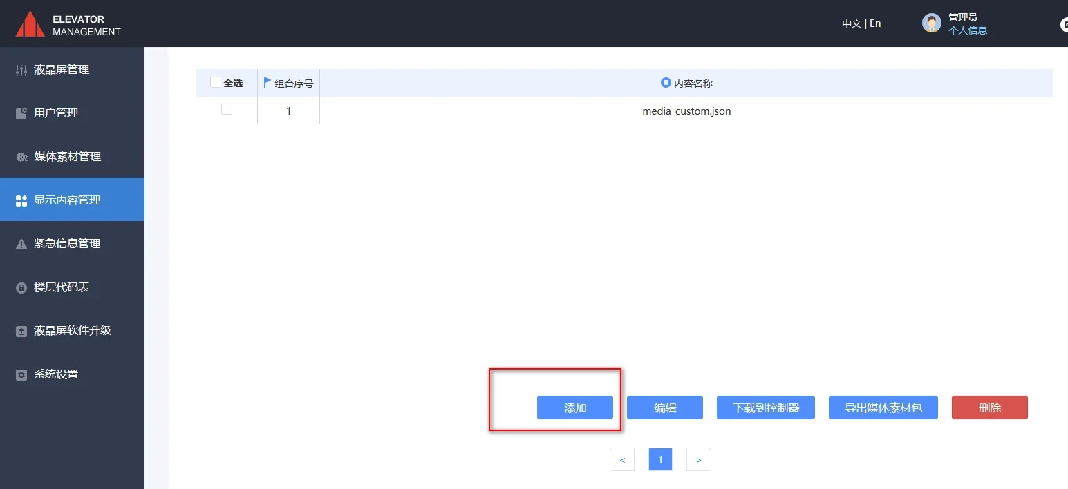
Figure 4-2 Display content management interface
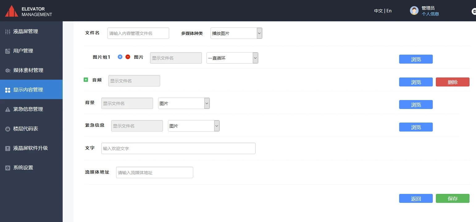
Figure 4-3 New display content
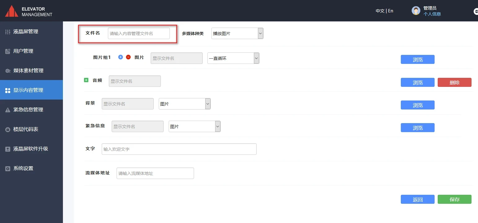
Figure 4-4 Enter the file name
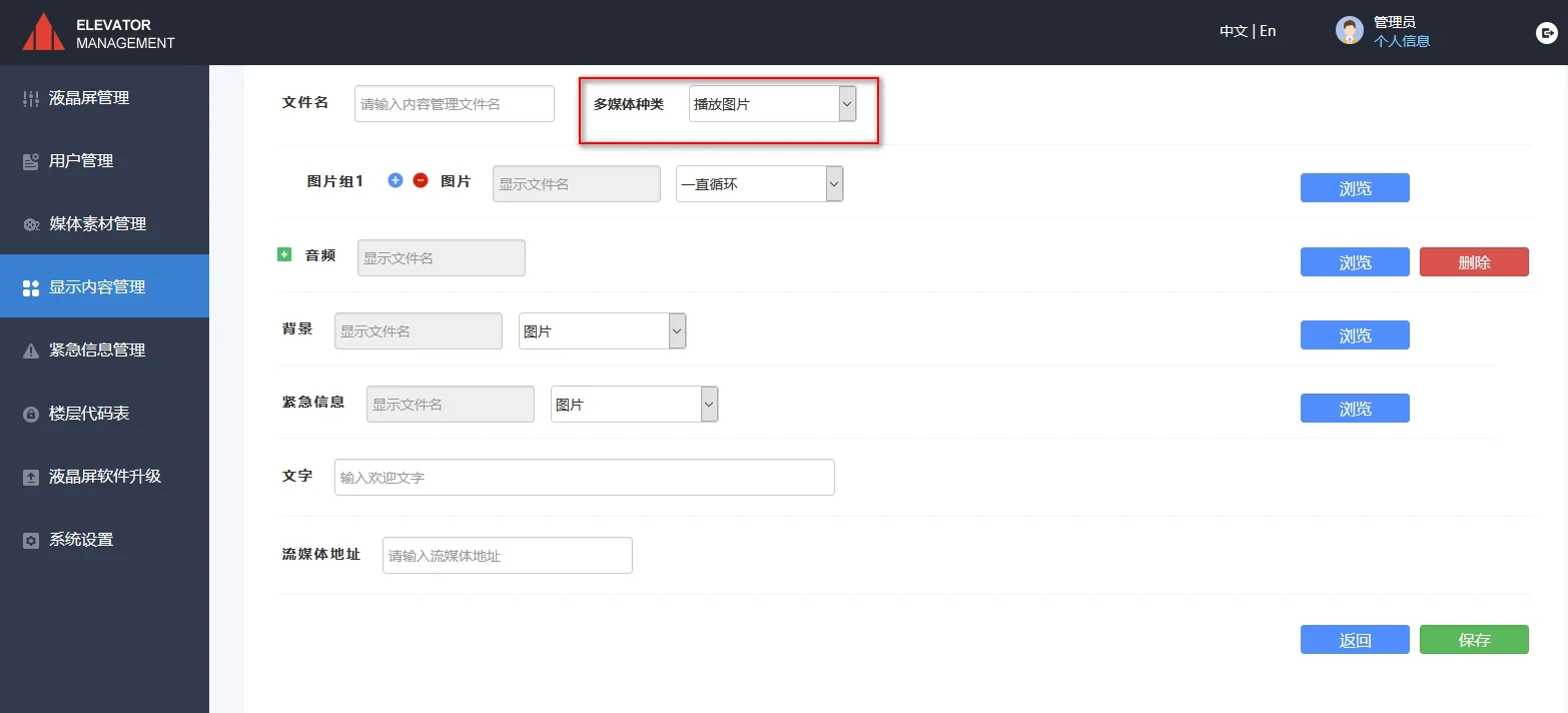
Figure 4-5 Select the type of material to play
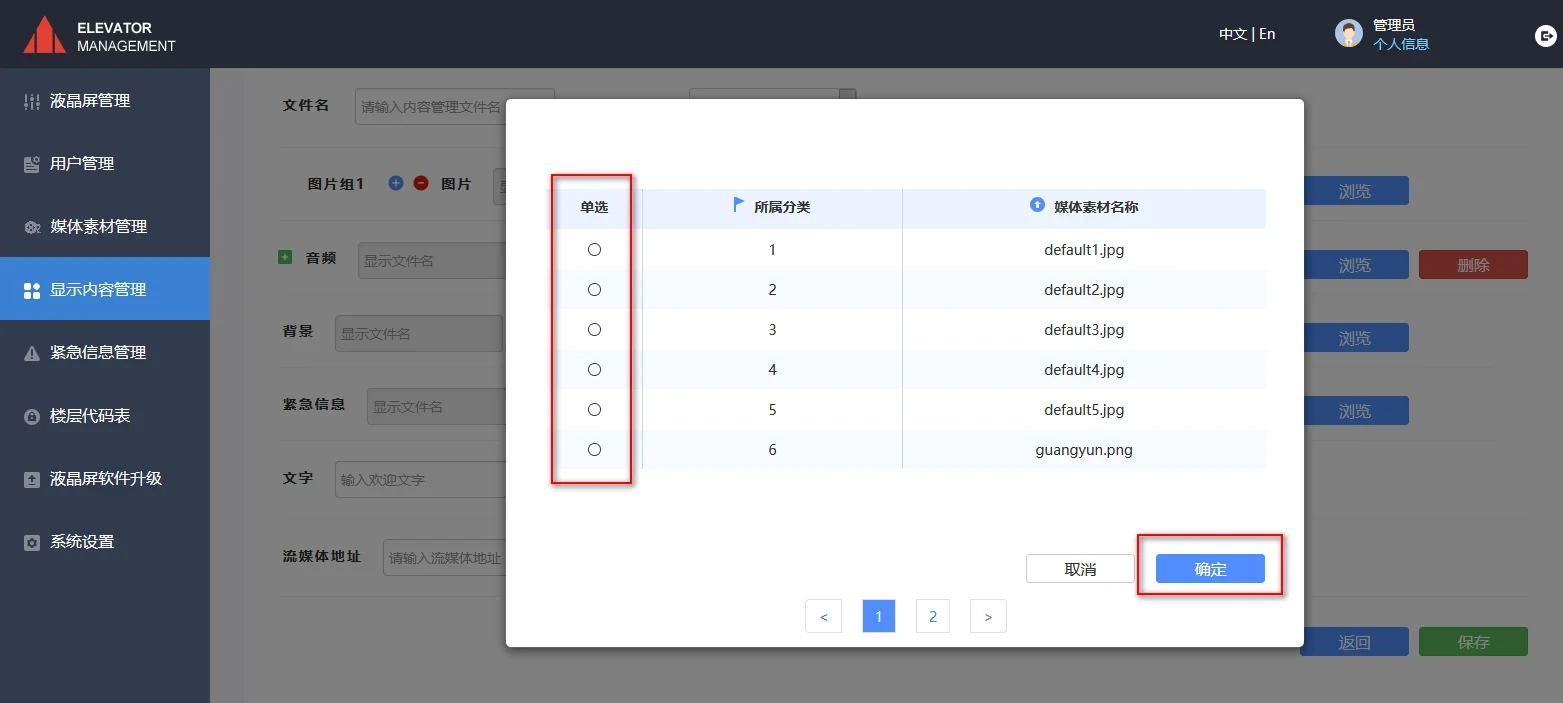
Figure 4-6 Select the required material file
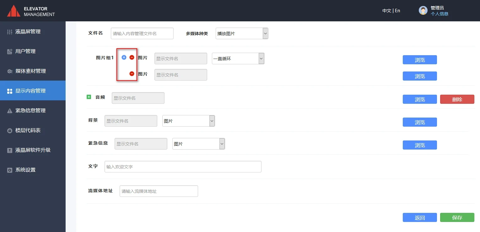
Figure 4-7 Add or delete operation
The picture group can select "loop play function", and the drop-down menu includes "loop forever, 10s, 30s, custom play time" options. As shown in Figure 4-9.
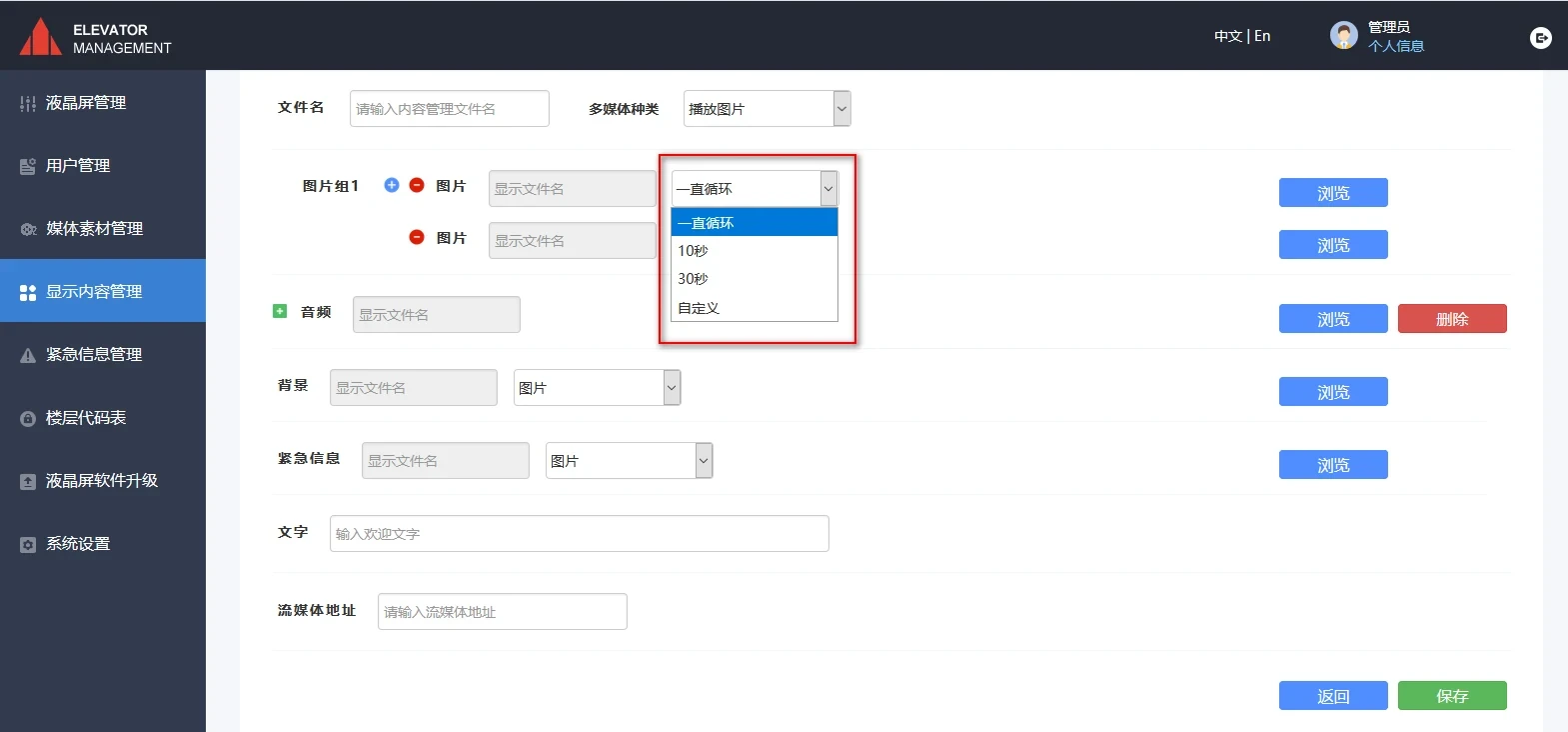
Figure 4-8 Picture loop playback
The video group can select the "loop play function", that is, you can choose to play a specific video in a specific time period of a specific week. In Figure 4-9, click the drop-down menu and select "Loop in a specified time period", then select a specified time period (as shown in Figure 4-11), and click "Repeat" to select the loop period, as shown in Figure 4-12.
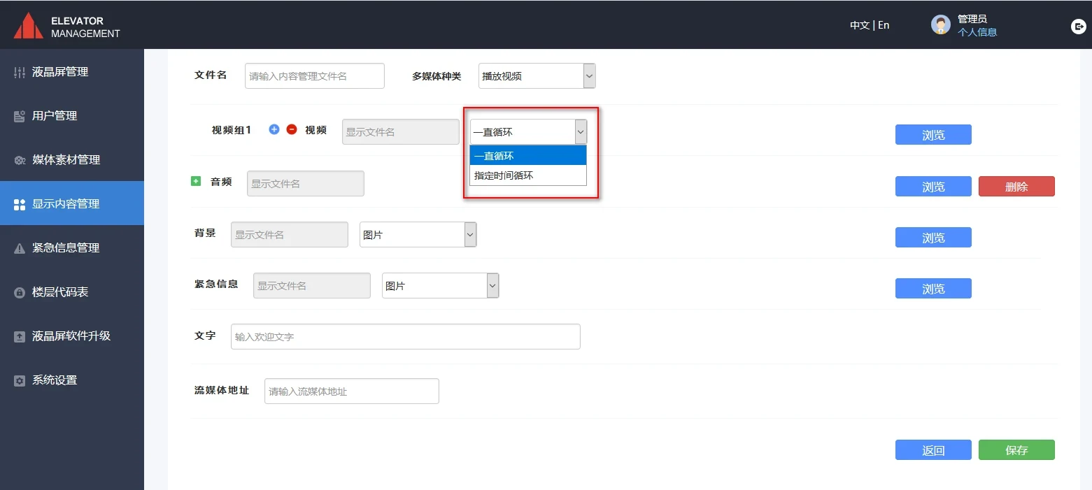
Figure 4-9 Video loop playback
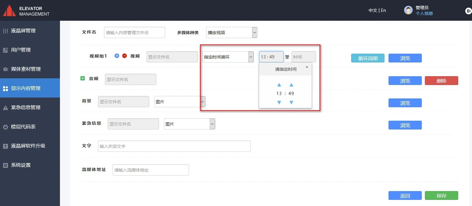
Figure 4-10 Specifying a time period cycle
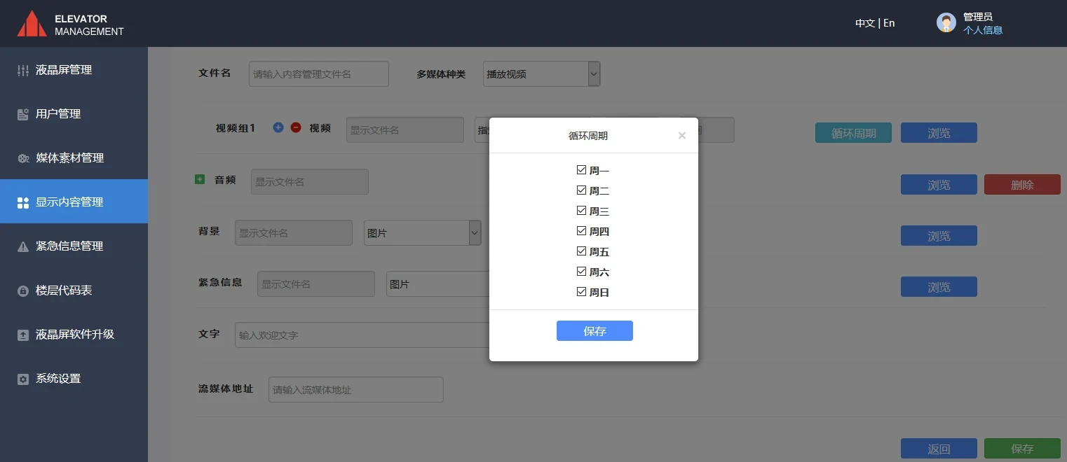
Figure 4-11 Selecting the cycle period
After clicking the "Browse" button for audio, the interface shown in Figure 4-12 appears. Check the desired audio and click "OK". This audio file can be used as background music when playing pictures. In the text box to the right of "Text", you can enter scrolling subtitles (as shown in Figure 4-13). Connect the mouse to the USB interface of the baseboard (bit number CN30), and click the upper left corner of the LCD screen to display the configuration menu. In this menu, select the three speeds of fast, medium, and slow to change the "scrolling rate" of the scrolling subtitles. After clicking the "Browse" button for background, the interface shown in Figure 4-14 appears. Check the desired background and click "OK". This picture file can be used as the background picture of the controller LCD screen. After clicking the "Browse" button for emergency information, the interface shown in Figure 4-15 appears. Check the desired background and click "OK". This picture file can be used as the background picture of the controller LCD screen when playing emergency information.
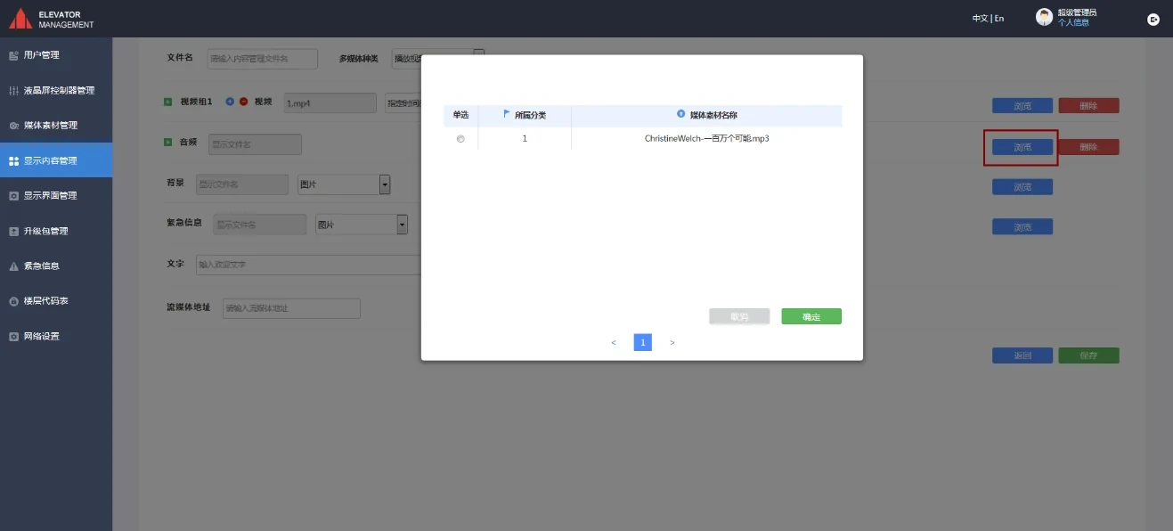
Figure 4-12 Selecting an audio file
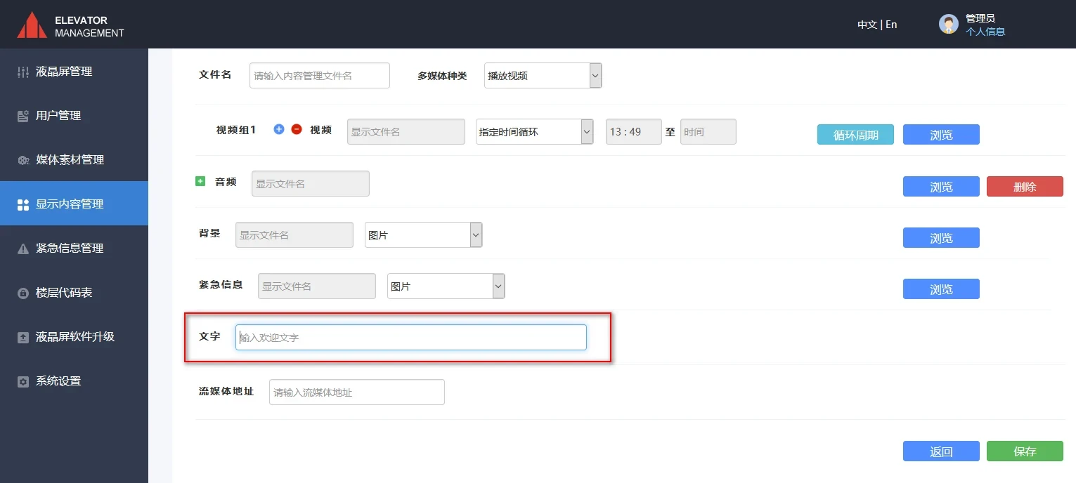
Figure 4-13 Input scrolling subtitles
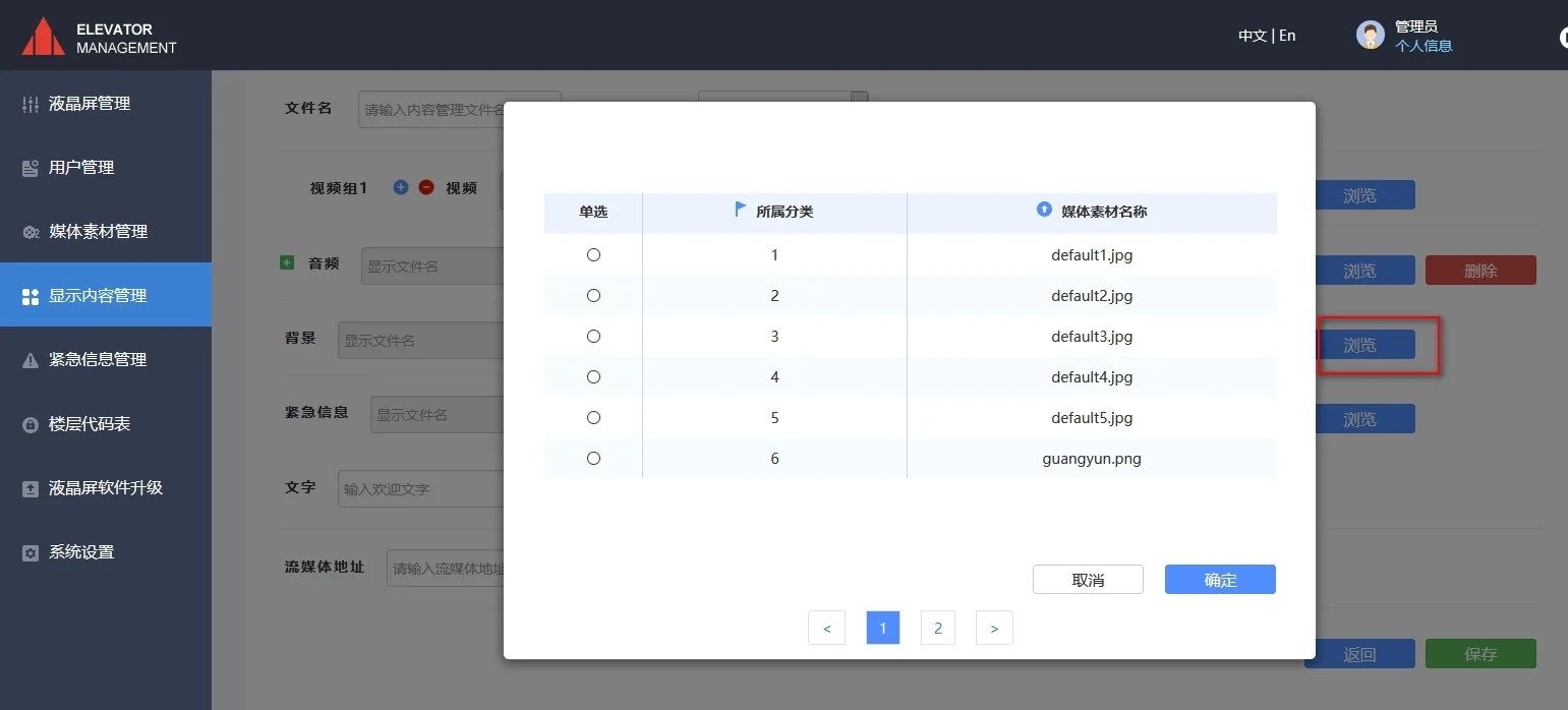
Figure 4-14 Select background image
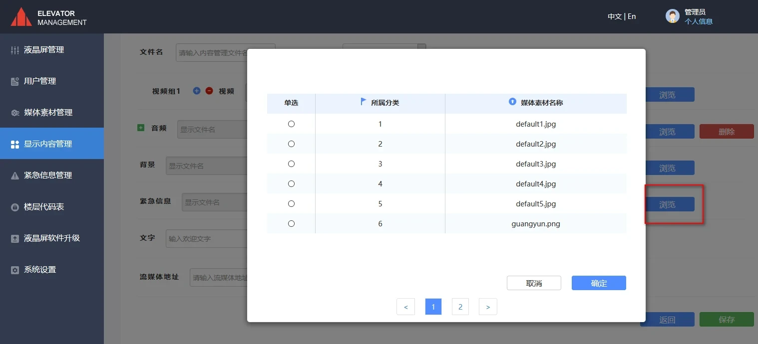
Figure 4-15 Select emergency information background image
5. LCD screen management (display content push)
Select "LCD Screen Management" on the left column, check the "Controller Name" of the content to be pushed [Note: The controller name of the baseboard can be modified directly in the text box below "Controller Name"], click the "Distribute Display Content" button in Figure 5-1 (you can also select the display content to be distributed in the display content management and download it to the controller), and the content can be pushed.
[Note: The display content required by the controller LCD screen must first be distributed to the controller in the LCD screen management, and then the display content management can be distributed to display correctly]
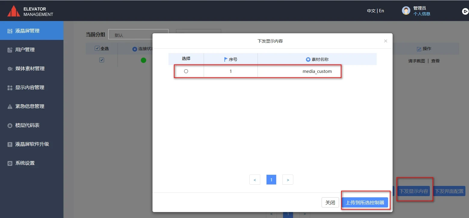
Figure 5-1 Sending display content
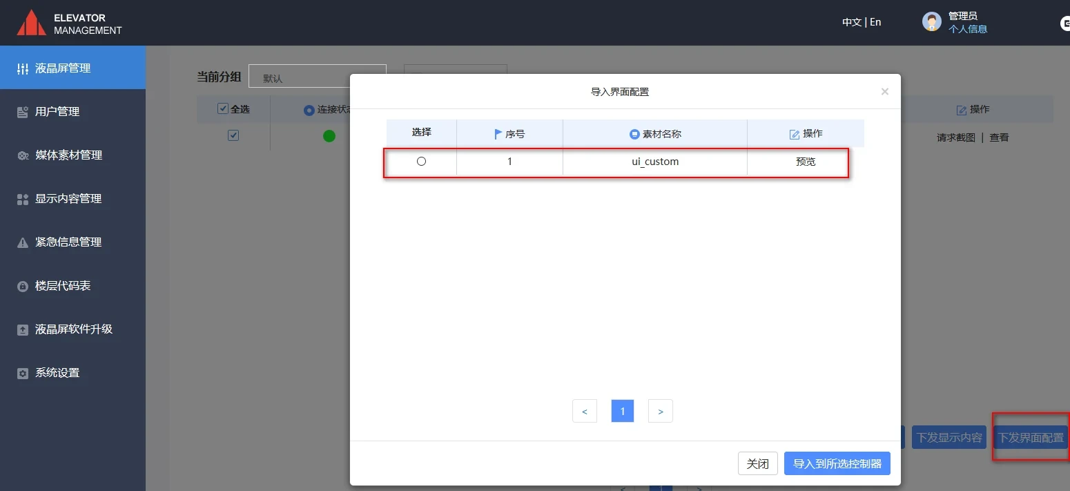
Figure 5-2 Sending interface configuration
6. Streaming media (provided by the company when selected by the customer)
1. encoder settings
① Connect the Ethernet interface of the streaming encoder to the network port of the PC with an Ethernet cable.
② Set the computer IP address to: 192.168.0.* (Note: * can be any number from 0-254 except 31).
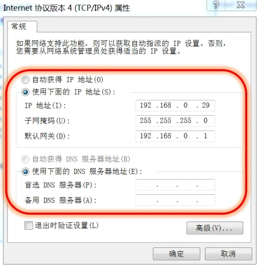
Figure 6-1 Setting the computer IP address
③ Open the browser and input 192.168.0.31 to enter the encoder backend settings page (user name: admin password: admin).
④ Modify the network setting parameters according to Figure 2.6-2.
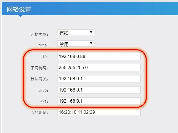
Figure 6-2 Setting network parameters
⑤ After the modification is completed, click the Set button, and then click Restart.
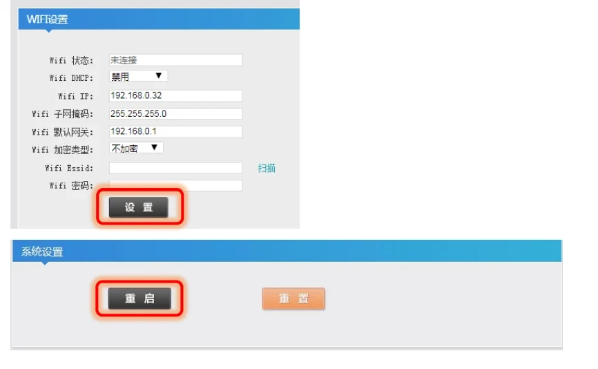
Figure 6-3 Restart after setting is completed
⑥ Open the browser and input: 192.168.0.88 (IP address is subject to on-site configuration) to enter the encoder backend setting page (user name: admin password: admin).
⑦ Refer to Figure 6-4 to modify the mainstream encoder parameters. After the modification is completed, click the "Set" button.
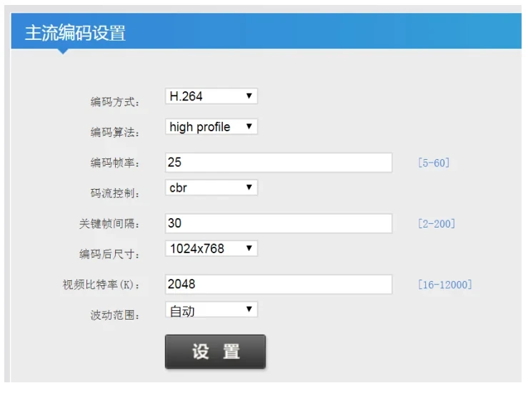
Figure 6-4 Setting the parameters of the mainstream encoder
⑧ Refer to Figure 6-5 to modify the mainstream protocol settings. After the modification is completed, click the "Set" button.
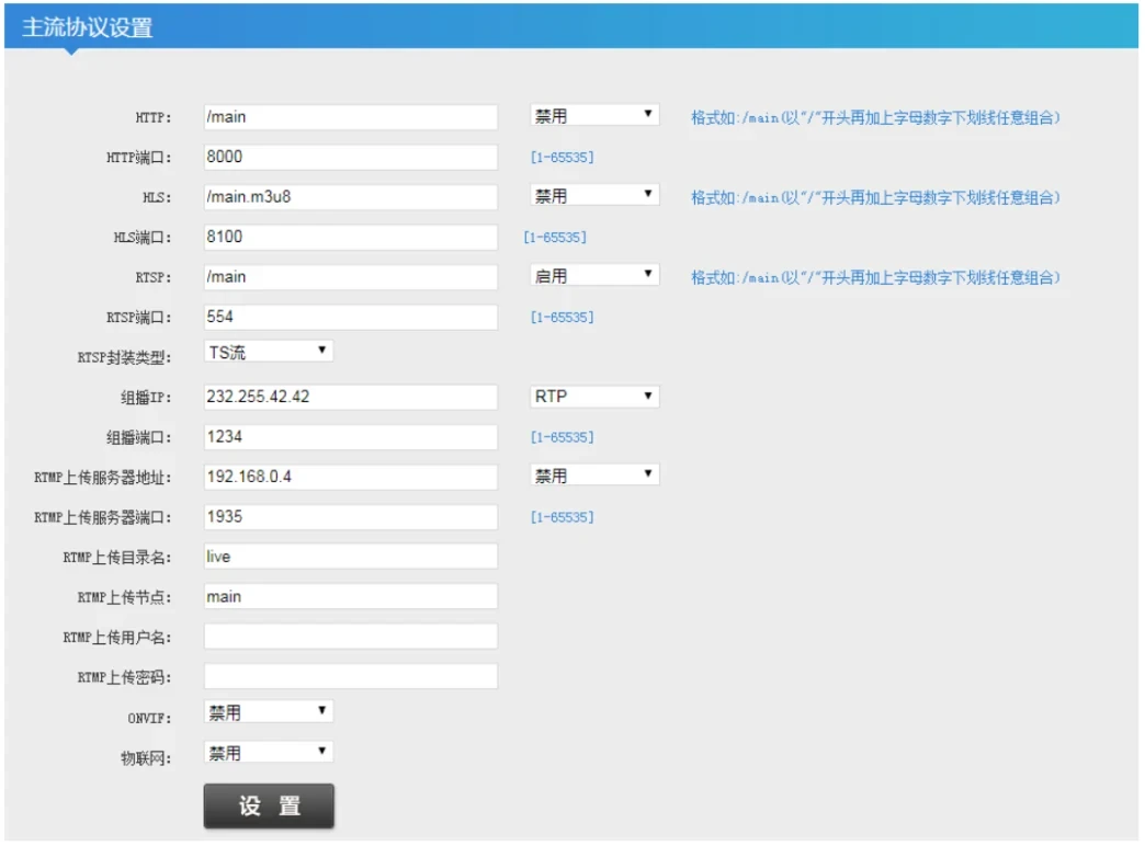
Figure 6-5 Setting mainstream protocol parameters
⑨ Refer to Figure 6-6 to modify the audio encoder settings. After the modification is completed, click the "Set" button.
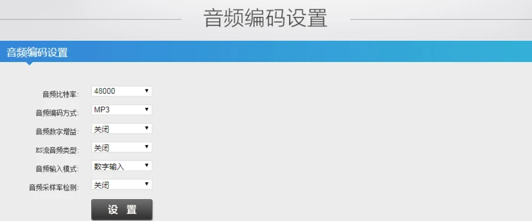
Figure 6-6 Setting audio encoder parameters
⑩ After completing the configuration required above, click the Restart button and wait for the restart to complete.
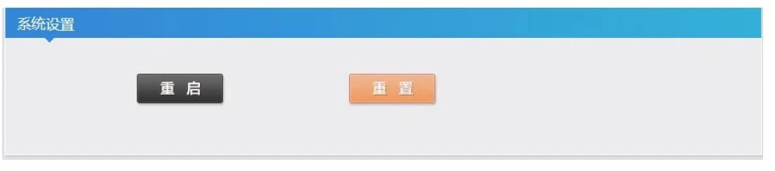
Figure 6-7 Restart
⑪ Open VLC player, select “Open Network Stream” and enter the projection connection.
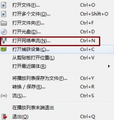
Figure 6-8 Opening the network stream
⑫ Open the background status display page, find the mainstream real-time browsing item, and copy the RTSP live broadcast address.

Figure 6-9 Copy RTSP live broadcast address
⑬ Paste the RTSP live broadcast address into the network streaming network item and click Play.
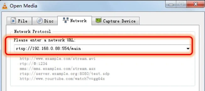
Figure 6-10 Paste RTSP live broadcast address
⑭ Open the EMIDS host computer page, add or edit the display content management. Paste the RTSP live broadcast address into the streaming media address, save the download and send it to the controller.
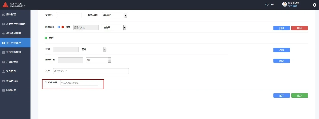
Figure 6-11 Paste RTSP live broadcast address
7. Host computer upgrade
Select "System Configuration" on the left column, click the "Upload Upgrade Package" button, click the "Browse" button in the pop-up window, select the upgrade package with the suffix "war", click the "Upload" button, and the upgrade is successful after the upload is completed.
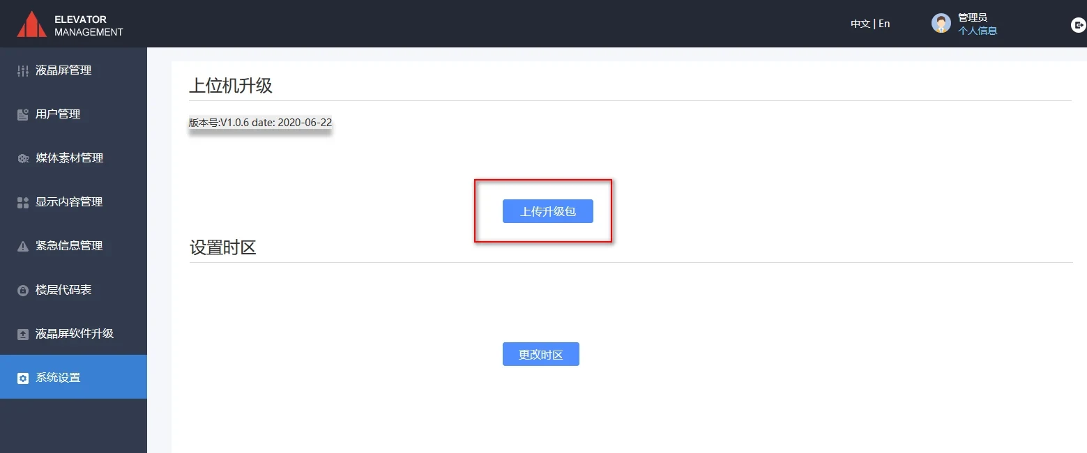
Figure 7-1 Host computer upgrade
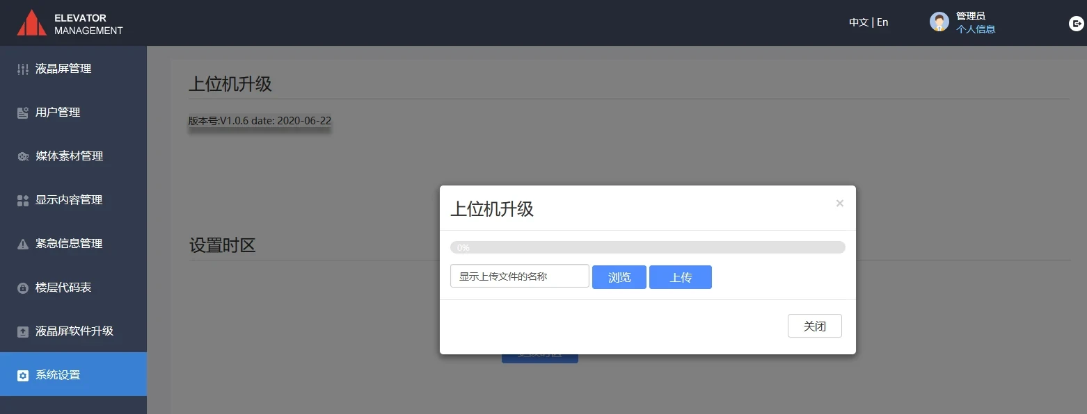
Figure 7-2 Upload upgrade package


