
1. Main Circuit (MC)
1.1. Overview
The MC circuit can be divided into the incoming pArt, the main circuit part and the outgoing part.
The incoming part starts from the incoming pile, passes through the EMC link (filter, reactor, etc.), and then enters the Inverter component through the control contactor #5 (enters the rectifier component when there is energy feedback). The outgoing part starts from the output of the inverter component, passes through the DC-CT (current transformer), may pass through the EMC link (reactor), and finally connects to the outgoing pile.
The main circuit part is the core part of the entire MC circuit. According to the characteristics of AC-DC-AC variable frequency drive, it is divided into the rectifier part, the DC part and the inverter part.
There are two types of rectifier parts, uncontrolled rectification and controlled rectification.
The uncontrolled rectification is a three-phase full-wave rectification of a diode bridge stack. The input is a three-phase cable #5, and the output is a busbar connected to the capacitor of the DC part. The core device of the rectification is a three-phase full-wave rectifier diode bridge stack installed on the heat sink. There is no phase sequence requirement for the uncontrolled rectifier input, but for the convenience of future maintenance, it should still be wired according to the drawing. The output is "P" and "N". P is connected to the positive pole of the capacitor, and N is connected to the negative pole of the capacitor. Since the capacitor is an electrolytic capacitor, the output polarity must not be reversed.
Note: The general rectifier output line is a busbar. However, the busbar may be assembled and connected by several components. After disassembly and maintenance, pay attention to correct installation.
The input and output of the controlled rectifier are the same as those of the uncontrolled rectifier, but the R and S phases of the #5 output pass through the rectifier DC-CT. Since the phase sequence of the controlled rectifier current feedback must be the same as the grid voltage phase sequence, the R and S phases cannot be reversed.
The core component of the controlled rectifier is a three-phase full-bridge controllable module. Depending on the type of elevator and the specifications of the elevator, IGBT or IPM is used. Its control signal source is the same as the inverter, which is the E1 board, or the additional E2 board. In some introduced elevators, energy feedback is an optional function, and its control signal source is the F1 board.
The main functional components of the DC part are electrolytic capacitors and equalizing resistors, and the connecting components are busbars. Since the power voltage is 380V, the main circuit capacitors are arranged in a two-stage series connection. Capacitors cannot be directly connected in series, otherwise the two series capacitors cannot evenly distribute the voltage. Therefore, two series equalizing resistors are connected in parallel on both sides of the capacitor. As long as the resistance value is the same, the steady-state voltage of the capacitor must be the same.
If it is a non-energy feedback elevator, the DC part also has a regeneration function, which consumes the regenerative energy by heating the resistor. This part of the function is mainly realized by the regeneration resistor and the regeneration module. In terms of electrical connection, the capacitor, the regeneration module and the regeneration resistor form a series circuit. When the capacitor voltage is high to a certain level, the regeneration module is turned on, and the regeneration energy is consumed by the heating of the regeneration resistor.
The inverter part is basically the same as the rectifier part, and can be understood symmetrically in terms of electrical principles. The input is the DC side "P" and "N", and the output is the motor drive voltage U, V, W. Two or all of the three-phase lines are output, passing through the DC-CT for motor current feedback, and then entering the outgoing line part.
Whether it is the rectifier or the inverter part, as long as it is controllable, there will be a SNUBBER component on the module to absorb the voltage spike pulse formed by the circuit inductance when the upper and lower bridge arms are commutated. If it is a discrete IGBT module, a SNUBBER printed board will be installed on the module, and if it is an IPM module, a non-inductive capacitor will be connected between "P" and "N".
In addition, in the MC circuit, there is also a control part with the drive printed board as the core. Its main function is to detect the state of the main circuit and provide specific module control signals.
The detection part is aimed at the incoming line side, whether there is energy feedback or not, the grid voltage phase deficiency and other abnormalities are all content that must be checked.
If it is energy feedback, the phase of the input R and S phase currents and the grid voltage will also be checked.
For the DC part, the control part checks the capacitor voltage. Some early model elevators will also check the DC current to determine whether there is overcurrent (E5).
For the output part, it is necessary to check the two-phase or all currents of the motor.
Note: The motor voltage is not within the inspection range.
The control part outputs the control signal of the module, and the signal modulation method is PWM (the principle is not expanded). However, it should be noted that these signals are transmitted using twisted pair cables. Whether the twisted pair wiring path is disturbed and whether the twisted pair connection is reliable are all closely related to whether the main circuit can operate stably.
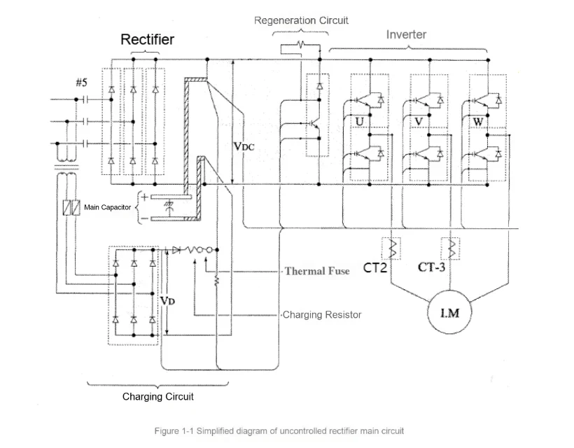
The schematic diagram of the uncontrolled rectifier main circuit is as follows:
1.2. General steps
The MC circuit is directly connected to the power grid. In addition, the main circuits are currently frequency-converting drives and closed-loop control. Therefore, once an abnormality occurs in the main circuit, it will cause an emergency stop at a very fast speed, and even damage to components in serious cases. Moreover, it is difficult to power on and repeat the inspection before the fault is eliminated. Therefore, troubleshooting the main circuit requires strong technical capabilities, especially a certain understanding of power electronics.
1.2.1. General principles to be followed in troubleshooting main circuit faults
1) The three-phase circuit of the main circuit must be completely symmetrical
All connected components on the main circuit are exactly the same in terms of connection method, electrical parameters (resistance, capacitance, inductance), etc. The principle is that for the drive circuit to work normally, the three phases must be "balanced". If any situation on any phase is found to be significantly different from the other two phases, the fault point is likely to be hidden in these differences.
2) The three-phase connection of the main circuit must follow the order on the drawing
In addition to the correct connection of the phase sequence on the main circuit, the control part also needs to detect various parameters of the main circuit input and output lines as mentioned above. These inspection circuits must also be consistent with the phase sequence of the main circuit. This is easy to overlook during inspection.
1.2.2. Method of opening closed-loop control
In view of the closed-loop control feature of the drive circuit, opening the closed-loop circuit when checking the drive fault will be of great help in further judging the problem. There are two commonly used opening nodes:
1) The node between the traction machine and the inverter output.
The common method is to disconnect the power cable of the traction machine first, and then observe the operation of the elevator. If it returns to normal, the fault may be on the traction machine side. If there is no change, the fault point should be on the control cabinet side.
2) The operation of #5 and #LB.
This method is often used in the case of energy feedback function. If #5 is released soon after the action and #LB has not been attracted, it is more likely that the fault is on the rectifier side. If #LB has been attracted, whether the brake is open or not, the inspection focus can be placed on the inverter side first.
1.2.3. Judge by fault code
For the phenomenon of repeated emergency stop faults, the fault code display on the P1 board can better distinguish whether it is a rectifier side or an inverter side fault; or a voltage fault or an overcurrent fault.
Note: When observing repeated faults, please note that the P1 board needs to be reset after each observation to clear the historical faults. In addition, if the emergency stop occurs instantly, in addition to observing the current fault, there are also historical faults that can be checked.
1.2.4. (M) Elevator drive failure in ELD
(M)ELD operation mode is a special mode of elevator operation. Generally, the elevator will choose to run in the regeneration direction at this time. If the weighing value is inaccurate, the elevator will be torque protected and run in the opposite direction. If the emergency stop protection occurs in both directions, the (M)ELD will stop power supply. Therefore, it is very important to ensure that the weighing data is good before the (M)ELD runs. If the elevator has a serious back-dragging phenomenon when starting at any floor, it needs to be eliminated before the (M)ELD runs. In addition, in order to take into account the only electric state in the (M)ELD operation-balanced load-the (M)ELD running speed design is based on the motor induced potential and battery voltage. Once any situation causes speed deviation, the balance between the motor's induced potential and the main circuit voltage will be broken, and the elevator will also enter an emergency stop.
Regarding the failure of the (M)ELD device, most of them are involved in the PS part. Generally, if the contactor of the (M)ELD device operates normally and the output voltage is normal, the main inspection direction for the (M)ELD not to operate normally is concentrated on the control cabinet side. At this time, it is important to observe the fault code display on the P1 board of the control cabinet, because once two emergency stops occur, the (M)ELD will be powered off and historical faults will no longer be visible.
1.2.5. Traction machine fault diagnosis
Because the traction machine is in a closed drive loop and the internal structure of the traction machine is relatively complex, the manifestation of the fault also varies, but it can be summarized into three situations: emergency stop, vibration, and abnormal noise.
Note: Due to the complexity of traction machine fault diagnosis, the cause of the fault can be reduced to confirming that the fault range is the traction machine.
1) Emergency stop failure
The main inspection method is to find the cause of the fault and the inspection direction from the minor fault code. In addition, some experiments can be done to further determine the problem based on the experimental phenomena. For example, if the elevator can run until the brake is opened after the traction motor power cable is disconnected, it is judged that the motor may be faulty. After that, you can connect 1 phase cable and run again (3 phases need to be tested 3 times). If the emergency stop phenomenon occurs, there is a greater possibility that the motor is faulty. Similarly, after the single-phase connection test, you can also perform a two-phase connection test. If the problem occurs again, it can also increase the possibility of motor problems.
2) Vibration problem
Mainly distinguish the location and load of vibration. For common vibration, it is necessary to first check other parts of the mechanical system, or whether the electrical system is disturbed, and then consider whether there is a problem with the motor. Generally, if the problem is suspected to be a motor problem, after checking and eliminating other mechanical parts, you can use the method of manually releasing the brake by powering off to check whether the vibration occurs again. Furthermore, if the vibration occurs in a specific operation, such as when it starts the first reverse operation under the same load, it is also likely that there is a problem with the traction machine. At this time, you can add a symmetrical load in the car (such as 20% to 80%, generally with the balance coefficient as the center point), and then observe whether the vibration also shows a symmetrical change. If so, the possibility of motor problems is further increased.
3) Abnormal noise problem
It can be divided into mechanical abnormal noise and electromagnetic abnormal noise. If it is mechanical abnormal noise, it can be confirmed by the above-mentioned method of power off and brake release. If it is electromagnetic abnormal noise, according to the principle of drive, it is necessary to check from the following three aspects:
a) Whether the brake is open, unilateral friction will affect the torque stability of the motor.
b) Whether the magnetic pole position is offset, after the offset, it is easy to cause current saturation and waveform distortion, causing abnormal noise of the traction machine.
c) Under symmetrical load, whether the abnormal noise also changes symmetrically.
Note: a) and b) can be adjusted and repaired on site, only c) needs to consider whether to replace the traction machine.
1.3. Common faults
1.3.1. Fault phenomenon: PWFH (PP) light is off or flickers
Possible causes and countermeasures:
1) Cause 1: Power supply phase loss or phase error
Countermeasures: Check whether the power supply voltage is within the standard range; change the power line phase sequence.
2) Cause 2: Printed board failure
Countermeasure: Replace the printed board (M1 board, E1 board or P1 board)
1.3.2. Fault phenomenon: Magnetic pole learning failure
Possible causes and countermeasures of the fault:
1) Cause 1: The encoder is poorly assembled
Countermeasures: Confirm that the encoder is securely fixed; use a dial gauge to measure the concentricity of the encoder when it rotates.
2) Cause 2: The encoder cable is defective
Countermeasures: Check whether the encoder cable is damaged or extended by itself.
3) Cause 3: The encoder or P1 board is defective
Countermeasures: Replace the encoder or P1 board.
4) Cause 4: Parameter setting error
Countermeasures: The traction machine or left and right parameters are wrong.
1.3.3. Fault phenomenon: Frequent failure to restart, fault display E02
Possible causes and countermeasures of the failure:
1) Cause 1: Poor heat dissipation of the module
Countermeasures: Apply thermal grease to the back of the module, evenly and with a thickness that is just thick enough to prevent the metal plate on the back of the module from being visible; check the fan speed. If the air volume decreases, you need to clean the dust or replace the fan; check whether the protective film on all ventilation holes in the control cabinet has been torn off. If not, be sure to clean it up without any residue; check the installation position of the control cabinet. The side ventilation holes must be at least 5CM away from the wall and at least 3CM away from the back; check the temperature in the computer room. If it is too high, increase ventilation or install air conditioning.
1.3.4. Fault phenomenon: overcurrent
1) Reason 2: Driver mismatch
Solution: Write the correct driver
2) Reason 3: Poor brake adjustment
Solution: Check brake gap and synchronization according to adjustment process
3) Reason 4: E1 board or module is bad
Solution: Replace inverter components (E1 board and module, etc.)
4) Reason 5: Traction motor is bad
Solution: Check whether the traction motor coil is short-circuited to ground
5) Reason 6: Current transformer is bad
Solution: Check the connection line from current transformer to printed board; replace current transformer
2. Power supply circuit (PS)
2.1. Overview
Regardless of the type of elevator, the names of commonly used power supplies are relatively unified. For example:
1) 79 power supply is used for driving and status feedback of the main contactor, so it is also the power supply of the safety circuit and door lock circuit. It is generally also the power supply of the brake circuit.
2) 420 power supply is generally used for the power supply of auxiliary signals. Such as the power supply of leveling switch, terminal switch, and functional relay.
3) C10-C00-C20 is generally the total power supply of the car, including the car top station and the control box (except for the car top station directly using C10-C20, other peripheral equipment uses C10-C00 and other AC100V power supplies (there is a switch power supply in the middle of the weak current equipment).
4) H10-H20 is generally the power supply for the floor station equipment. Except for the large arrival forecast lights in the floor station equipment, they are generally converted into low-voltage DC power supplies for the floor station equipment through the floor station power supply box.
5) L10-L20 lighting power supply.
6) B200-B00 other power supplies, generally used as power supplies for special equipment in certain types of elevators.
Note: The power supply with the same name may have different voltages in different ladders. For example, the voltage of #79 in the machine room is the same as that of #420. For specific voltages, please refer to the debugging information of the ladder.
The power supply system of the elevator includes a conventional power supply system and an emergency power supply system.
The most common conventional power supply systems are the control transformer power supply mode and the DC-DC power supply mode.
Under the control transformer power supply mode, the external 380V power supply enters the transformer, and then generates different levels of voltage according to the difference of the secondary winding. These power supplies enter the power supply board, part of which is rectified to generate the DC power supply used by the system, and the other part is directly used as the AC power supply used by the system, and then output from the connector of the power supply board.
In the case of excessive capacity of the floor station or the need for safe voltage, the control cabinet also has additional transformers and safety lighting transformers as supplements to the control transformer.
Under the DC-DC power supply mode, the external 380V power supply is first converted into a DC48V main power supply through a power module, and then the main power supply is inverted into various DC power supply voltages through a certain DC-DC conversion circuit.
Note: The difference between the DC-DC power supply of imported technology elevators and self-developed technology elevators is that the imported technology elevators still retain the original AC power supply for the floor station power supply and the car top station power supply. This part of the power supply is still converted from the "transformer". The DC-DC power supply of the self-developed technology elevator is an integrated device, and the floor station power supply and the car top station power supply are converted to DC at the same time.
The emergency power supply system mainly refers to the (M)ELD system. According to the speed of emergency power switching after power outage, it can be divided into two categories: one is that after the external power grid is powered off, it takes a period of confirmation time before the (M)ELD starts working. Once the (M)ELD enters the working state, even if the external power grid resumes power supply, it will be isolated from the elevator power supply system until the (M)ELD operation ends. The other is that after the external power grid is powered off, the emergency power supply keeps the DC main power supply powered.
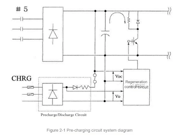
Although the main circuit pre-charge/discharge circuit (non-energy feedback) seems to be part of the main circuit, it should also be considered as part of the power circuit in terms of its circuit properties. Its working state is that when the elevator is in the stopped state after power is turned on, the high-voltage direct current generated by the control transformer or DC-DC power supply is charged to the main circuit through the current limiting resistor. When the elevator is running, the pre-charge circuit is almost cut off due to the closure of #5. After the elevator is powered off, its discharge circuit is connected, and then the residual energy on the main circuit capacitor is quickly released through the discharge resistor.
Note: The pre-charge/discharge circuit of energy feedback belongs to the main circuit in principle. For troubleshooting, refer to the relevant chapters of MC.
The simplified diagram of the charging circuit system is shown below:
2.2. General steps:
2.2.1. Conventional power supply system
The most common faults in conventional power supply systems are:
1) The fuse circuit breaker is disconnected. For example, the fuse burns out or the circuit breaker trips.
2) The power supply voltage is abnormal.
3) The power supply system has a long line, and all elevator electrical equipment is related to it. A common fault is interference. Although the fault phenomenon seems to have nothing to do with the power supply and varies greatly, the fundamental solution is good power supply wiring.
When the fuse circuit breaker is disconnected, it is usually because of a short circuit or breakdown in the power supply line or load. Generally, the total output of this power supply is disconnected first, and the voltage is checked to see if it is normal. If the voltage is too high, check whether there is a problem with the power supply device itself. Then disconnect all loads on this power supply, and use an "insulation meter" to directly check whether there is any insulation damage. Finally, connect the loads to the power supply one by one in order. Once a fuse is burned or the circuit breaker trips, it can be confirmed that this component is damaged and needs to be replaced.
When checking the insulation of the cable, if the electrical components are far away from the control cabinet, you can use spare wires to temporarily create a "loop", and then check with a multimeter or "insulation meter".
Note: The spare line must be in good condition, so that once a problem is found, it can be confirmed that the problem is with the line being checked. (This type of method should be careful not to introduce new possibilities that may complicate the problem)
The key point of checking and handling abnormal power supply voltage is to first distinguish whether it is a power supply problem or a load problem. You can also disconnect the total output of the power supply where the abnormal voltage occurs and measure the power supply voltage. If the voltage is abnormal, check whether the input of the power supply is voltage deviation or the three-phase power supply is unbalanced or lacking a phase.
If the input voltage is too high or too low, the control transformer can adjust the input tap. DC-DC has an automatic control mechanism and does not need to adjust the voltage. Once the problem of too high or too low occurs, the power supply device itself may be faulty and needs to be replaced for testing.
If the three-phase power supply is unbalanced or lacking a phase, you need to contact Party A to rectify the power supply.
Poor wiring of the power system can easily cause abnormal operation of the weak current printed circuit board. It is difficult to check and confirm this type of problem later. It can only be checked and rectified according to the main wiring principles. If necessary, the wiring needs to be changed for testing. The wiring principles are:
1) Separation of strong and weak current. Strong current and weak current (especially signal lines) cannot be routed in the same wire trough. The wire trough must be reliably grounded to prevent crosstalk from electromagnetic radiation.
2) Parallel routing of possible interference lines should be minimized, and it is best to use a right-angle orthogonal wiring method.
Note: According to experience, interference mostly occurs when the motor power cable interferes with the signals in the accompanying cable and shaft cable, and when the AC power supply in the accompanying cable and shaft cable interferes with the communication line.
2.2.2. Main circuit pre-charge/discharge circuit
The main fault phenomena of the main circuit pre-charging/discharging circuit are:
1) Abnormal main circuit charging voltage, including charging voltage too high or too low. And often accompanied by main circuit charging resistor overheating, temperature fuse melting and other phenomena.
2) Abnormal main circuit charging time. At this time, the elevator can no longer start and can be confirmed from the fault code.
For the fault phenomenon in 1), you can disconnect (remove) all circuits connected to the DCP and only keep the circuit connecting the charging device to the DCN. Then use a multimeter to measure the output interface voltage of the pre-charging circuit in the power supply. If it is normal, the power supply problem can be ruled out. Otherwise, check and replace the power supply.
Then confirm whether the capacitor voltage has been released, and then connect the "pre-charge" circuit to the circuit connected to the DCP. After the elevator is powered on again, check whether the capacitor voltage can rise to the normal voltage value. If not, measure the voltage of each component or both ends of the cable on the pre-charge circuit. When the capacitor voltage is stable, measure the line or component with a large voltage drop, which is the focus of inspection. If the voltage drop section is normal, the capacitor body and the voltage-equalizing resistor connected in parallel with it need to be checked.
If the pre-charging circuit charges normally after being connected alone, then abnormal discharge has occurred in other circuits or components connected to the DCP. The routine inspection directions include: rectifier module, regeneration resistor circuit, discharge circuit, bus bar and non-inductive capacitor, etc.
For the problem in 2), the inspection process and scope are roughly similar to 1), except that a certain abnormal discharge power cannot catch up with the power of the pre-charge circuit, and the voltage can eventually reach the predetermined charging voltage, but the time is extended. The inspection needs to be more careful than handling the fault in 1).
2.2.3. (M)ELD Troubleshooting
(M)ELD From the power supply perspective, common faults include:
1) (M)ELD does not start
2) (M)ELD power supply voltage is abnormal
3) (M)ELD power supply is abnormally terminated
The starting condition of (M)ELD is that the control cabinet is powered off, and the judgment standard is to detect the #79 power supply of the control cabinet. If there is no power, the (M)ELD control system starts to work. Therefore, the inspection ideas and steps for this fault phenomenon are:
a) Check whether the (M)ELD control device can receive the corresponding #79 power supply signal when the control cabinet is powered off;
b) Check whether the battery voltage and wiring of the (M)ELD control device are normal;
c) Check whether the switch circuit that controls the start and stop of (M)ELD is normal, and whether all switches have reached the "ON" state
Note: Due to the particularity of the machine-less room, there are control (M)ELD switches in many places such as HIP, control cabinet, and auxiliary cabinet, which may easily lead to omissions and cause the (M)ELD to fail to work.
For abnormal (M)ELD power supply voltage, first check the battery voltage. If the battery voltage is low, consider whether the charging circuit is abnormal (to avoid battery damage caused by the charging circuit being cut off). If there is a step-up transformer, it is also necessary to check whether the voltage taps and filter components of the transformer input and output are in good condition.
Once the (M)ELD starts to supply power normally, there will be no problem with the main part of the (M)ELD system. (M)ELD stops supplying power due to abnormality, resulting in interruption of (M)ELD operation. This is generally due to the detection of abnormality in the control cabinet during (M)ELD operation. For example, safety relay #89 is disconnected, long-term leveling without door zone signal, etc. This type of problem needs to be checked from the control cabinet, and will not be repeated in this power supply section.
2.3. Common faults
2.3.1. Fault phenomenon: Poor voltage of C10/C20, H10/H20 or S79, S420
Possible causes and countermeasures of the failure:
1) Cause 1: Poor input voltage
Countermeasure: Check whether the power supply voltage is within the standard range and adjust the transformer tap accordingly.
2) Cause 2: Transformer failure
Countermeasure: Check the input and output voltages on the transformer side.
3) Cause 3: DC-DC power supply device failure (if any)
Countermeasure: Check the input and output voltages of the DC-DC power supply device.
4) Cause 4: Poor line or grounding
Countermeasure: On the premise of confirming that the output voltage of the transformer or DC-DC power supply device is normal, check step by step whether the subsequent cables are bad or grounding.
2.3.2. Fault phenomenon: The printed board cannot light up
Possible causes and countermeasures of the fault:
1) Cause 1: 5V power supply is bad
Countermeasures: Check whether the 5V working power supply of the printed board is normal, and check the relevant circuits.
2) Cause 2: Printed board failure
Countermeasures: Check the printed board.
2.3.3. Fault phenomenon: transformer damage
Possible causes and countermeasures of the fault:
1) Cause 1: The output circuit is short-circuited to the ground
Countermeasures: Check whether the transformer output circuit is short-circuited to the ground.
2) Cause 2: Poor power supply
Countermeasures: Check whether the three phases of the power supply are balanced and whether they meet the relevant requirements of our company (for example: voltage fluctuation is within ±7%).
2.3.4. Fault phenomenon: (M)ELD function abnormality
Possible causes and countermeasures of the fault:
1) Cause 1: (M)ELD does not meet the start-up conditions
Countermeasures: Check the wires and components of the (M)ELD related circuits; check whether the switches of the (M)ELD related circuits are closed, especially for machine room-less elevators involving many switches, please confirm one by one.
2) Cause 2: Insufficient battery voltage
Countermeasures: Measure the battery voltage and replace it.
2.3.5. Fault phenomenon: abnormal pre-charge/discharge of main circuit
Possible causes and countermeasures of the failure:
1) Cause 1: Input power failure
Countermeasure: Check the power supply voltage and replace it.
2) Cause 2: Main circuit pre-charge/discharge circuit component failure
Countermeasure: Check the rectifier module, regeneration resistor circuit, discharge circuit, bus bar and non-inductive capacitor, etc.
3. Brake circuit (BK)
3.1. Overview
The brake circuit is currently divided into two categories, resistance voltage control and current control. Regardless of the brake control method, the brake circuit can be divided into a drive circuit and a contact feedback circuit from the perspective of circuit function.
3.1.1. Current control brake circuit
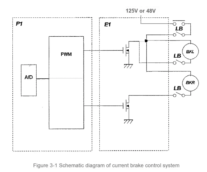
The brake circuit of the current control method is relatively simple in terms of system topology, and the brake contact feedback and coil drive are independent of each other. According to the wiring diagram, the typical coil drive circuit starts from the #79 or S420 power supply and supplies power to the control unit through the main contact of #LB (the control unit is the W2 board or E1 board). According to the elevator operation instruction, the control unit first controls #LB to attract and establish the working voltage of the control unit. Then the control unit outputs the brake control voltage according to the instruction, and the brake opens. During the brake opening process, the feedback contact moves as the armature opens. Feedback the action state of the brake armature to the control system. The power supply of the feedback contact is directly obtained from the power supply, and its signal is also directly input to the W1 board or R1 board.
The system diagram of the current control method is shown below:
3.1.2. Resistor voltage division control brake circuit
The circuit topology of the resistor voltage-dividing control method is more complicated than that of the current control method. The brake contact participates in the switching of the coil drive voltage.
When the brake is closed, the normally closed contact of the brake contact is connected, short-circuiting the voltage-dividing resistor. When #LB is energized, the brake coil is directly connected to the #79 power supply. After the brake coil is energized, the armature moves and the brake is opened. The armature makes the brake contact move, the normally closed contact is disconnected, the voltage-dividing resistor is connected to the brake circuit, and the voltage of the brake coil is switched to the holding voltage. The rear end of the brake contact is directly connected to the W1 board or the R1 board as a feedback signal of the armature action state.
Among the elevators currently on sale, there is an improved circuit for the most basic brake circuit mentioned above, which uses the normally open switch on the added brake contact to check the brake closure status. The detailed operation process is as follows:
The opening action is the same as the conventional brake circuit mentioned above. However, when closing, after #LB is released, the normally closed contact of #LB supplies power to the normally open contact circuit of the brake contact. But at this time, the brake is still in the open state, and the normally open contact is still in the closed state, so a high level is formed again on the brake feedback contact interface of the W1 or R1 board. If the brake is closed normally, the normally open contact of the brake feedback opens, and the brake feedback contact interface becomes a low level again. If the brake cannot be closed normally, the brake feedback contact interface is always at a high level before #5 is disconnected. Based on this level change, the program can determine whether the brake is opened and closed normally.
3.2. General steps
The fault phenomena of the brake circuit can be summarized as brake action fault, brake feedback fault and the combined fault of the two.
3.2.1. Brake action failure
Brake action failure is mainly caused by the failure of the brake to open on both sides or on one side, or the failure of the brake to close on one side. (If the brakes on both sides are not closed, the car will inevitably fall, which is beyond the scope of general troubleshooting)
For brake action failure, mechanical adjustment and electrical inspection can be performed first, but if the principles in the overview are used as a guide, the inspection can be carried out in the following order:
a) Check whether the brake coil power supply voltage is normal. Note that there is a full voltage pulse when the brake is opened, and then it switches to the maintenance voltage after the brake is opened.
b) Check whether the brake contact action position is normal. Abnormal action position will affect the brake opening action.
c) Check whether the mechanical parts of the brake are blocked.
d) Check whether the brake gap, torque spring, etc. are adjusted in place.
Note: Taking the ZPML-A series traction machine as an example, a lever mechanism is formed between the brake shoe, brake arm and electromagnetic coil. The stroke of the electromagnetic coil plunger and the gap opened by the brake shoe are proportional. That is, the brake gap determines the action distance of the electromagnetic coil armature. Since the optimal action distance of the electromagnetic coil armature is about 2mm, once the brake gap is adjusted too large, the stroke of the upper end of the brake armature will inevitably exceed the action stroke of the electromagnetic coil armature, resulting in insufficient torque when the brake is opened and cannot be opened.
3.2.2. Brake action status feedback and fault detection
When the brake action is normal, but the elevator stops suddenly or cannot be started again, and the brake action related fault code appears on the P1 board, there is a problem with the action position of the brake contact, the brake contact device itself, or its power supply and feedback signal circuit. The means of inspection include replacing the brake contact switch, checking whether its circuit is normal, and finally adjusting the contact action position.
Note: If it is a current-controlled brake or a brake controlled by a brake controller, the brake contact action position only needs to be adjusted within the electromagnetic coil armature action stroke, and it is generally better to adjust it to the center of the stroke. However, if it is a brake controlled by a resistor voltage divider, due to the inherent inconsistency of the electromagnetic coil's physical properties, it is necessary to leave enough full voltage (overexcitation) time for the brake on the slower side. Therefore, the brake contact action position should be close to the end of the brake opening stroke.
3.2.3. Comprehensive fault
If the brake does not work properly when it is opened, and the digital tube on the P1 board reports the brake-related fault code, it is necessary to conduct a complete debugging of the brake according to the process. For the ZPML-A series permanent magnet synchronous traction machine, it is a basic requirement to use the brake debugging device for adjustment.
3.3. Common faults
3.3.1. Fault phenomenon: The brake cannot be opened
Possible causes and countermeasures of the fault:
1) Cause 1: Abnormal voltage of the brake coil
Countermeasures: Confirm whether the voltage output from the printed board to the brake coil is normal; whether the connection line from the printed board to the brake coil is correct and reliable
2) Cause 2: Wrong brake contact action position
Countermeasures: Confirm whether the brake contact action is correct; adjust the brake contact action position (if the process permits)
3) Cause 3: Abnormal action of the brake mechanical parts
Countermeasures: Confirm whether the brake gap, torque spring, etc. are correct; adjust the brake-related parts (if the process permits)
3.3.2. Fault phenomenon: Insufficient brake torque
Possible causes and countermeasures:
1) Cause 1: Brake shoe wear
Countermeasure: Replace brake shoe
2) Cause 2: Abnormal operation of brake mechanical parts
Countermeasure: Confirm whether the brake clearance, torque spring and other operations are correct; adjust brake-related parts (if the process permits)
3) Cause 3: Abnormal brake surface
Countermeasure: Check for abnormalities (such as oil stains, etc.)
4. Safety circuit (SF)
4.1. Overview
All mechanical and electrical safety devices of the elevator system must be in a safe and effective state. The elevator car door and all floor doors are closed, which is the most important condition to protect passengers, drivers and other personnel from falling and shearing threats.
The safety circuit diagram is shown below:
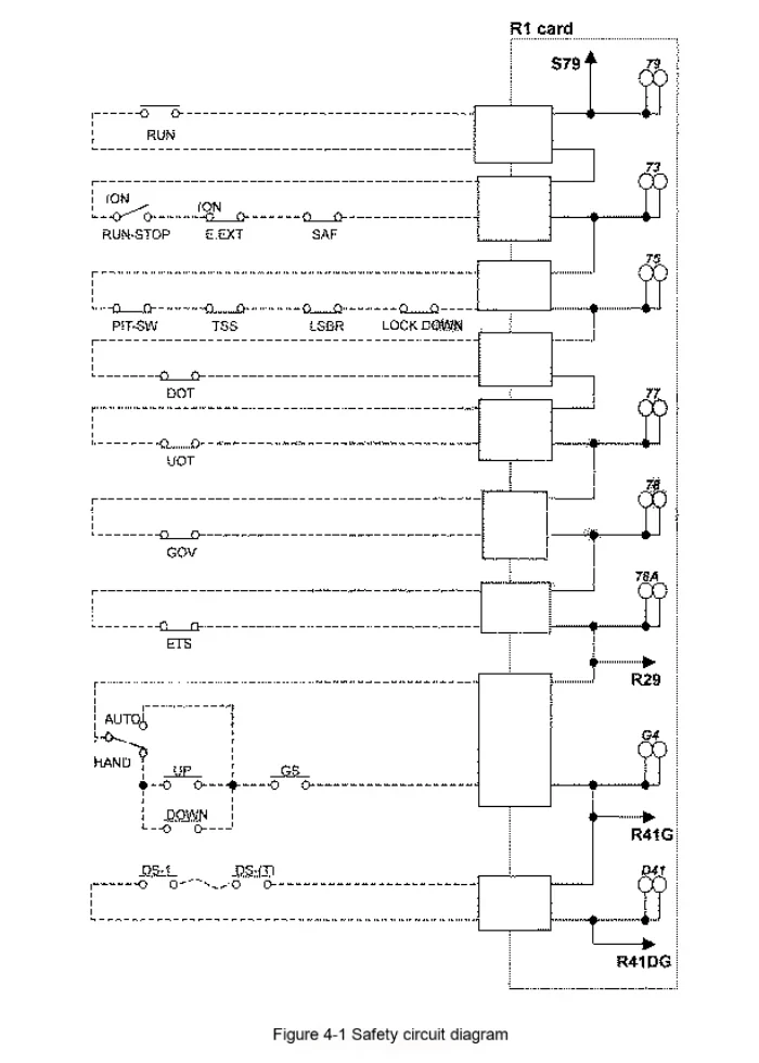
In the design of general elevator control system, all safety conditions are connected in series in a loop, which is called safety loop. The safety loop "ON" is the most basic condition for the elevator to start and run. The simplified elevator safety loop is shown in Figure 1. The switches of all safety components in the elevator are connected in series to control the safety relay (such as #89) (but after the P1 board is switched to C language program, #89 is changed to internal logic). As long as any of the safety components is switched, the power supply of the safety relay coil will be cut off to release it, and the alarm signal will be sent to the main control computer board. When the electrical safety circuit is activated to ensure safety, the elevator drive host should be prevented from starting or stopped immediately (by cutting off the main circuit contactor (such as #5)). The power supply of the brake should also be cut off (by cutting off the brake control contactor (such as #LB)). The switch function of the general safety loop is briefly described as follows:
The safety loop that the elevator is truly allowed to run includes the above-mentioned external mechanical and electrical safety device loops and the system control software diagnostic safety operating conditions. The normality of the external mechanical and electrical safety device circuits can be judged by the No. 29 indicator light being on or the voltage measurement of 00 (DC125V or DC48V). The No. 89 indicator light being on means that all safety conditions of the elevator meet the operating conditions.
Safety circuits are classified according to connection order and function, and are connected in the following order:
1) Safety circuit: Use #79 as power supply to connect switches in the machine room, car, pit, etc. in series;
2) Door lock circuit: Use safety circuit output #78 as power supply to connect car door lock and all hall door lock switches in series;
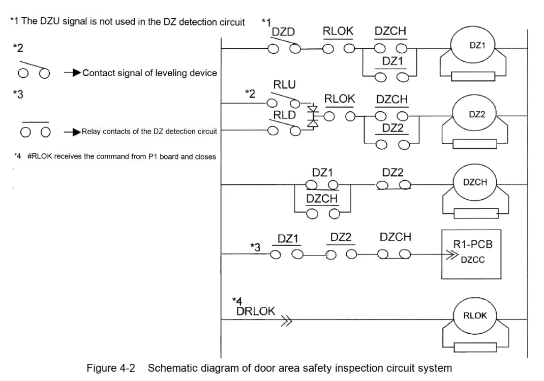
3) Door area safety inspection circuit: Use safety circuit output #78 as power supply. And connect in parallel with the door lock circuit. When the door area signal is checked intact and the elevator needs to open the door to run, this circuit is connected. If the door is closed, this circuit does not work.
4.2. General steps
4.2.1. Fault phenomenon and confirmation method
After #29 or #89 is disconnected, it can be directly confirmed by the status of the LEDs with the same name on the P1 board. Generally, when the circuit is disconnected, the relevant LEDs are off.
When a safety circuit failure occurs, if the elevator is in operation, it will show an emergency stop. More generally, as long as the safety circuit is disconnected, the elevator cannot be started again. Once the safety circuit is restored, if there are no other faults, the elevator will immediately enter the operational state.
If any part of the safety circuit is disconnected for some reason and then restored, the elevator will show an emergency stop and then automatically level, but it will not affect subsequent operation.
4.2.1.1. There are two ways to confirm safety circuit faults:
1) Determine whether the safety circuit or door lock circuit is disconnected based on the signal indicator lights (#29 #41DG) on the printed board.
2) Determine whether the safety circuit has been disconnected based on the fault code (applicable to instantaneous disconnection)
4.2.1.2. General method for finding the fault point of the safety circuit:
1) Stable disconnection of the circuit: The wiring method of the safety circuit has the characteristics of regional aggregation, that is, the switches with close installation positions are grouped together, and the line is connected back to the control cabinet to arrange a measurement point (also a short-circuit point). Therefore, these measurement points can be used to confirm which section of the safety circuit has a problem.
2) Instantaneous disconnection of the circuit: This type of fault is slightly more difficult to handle than 1). You can first check the status of each switch, and replace the test as long as you suspect there is a problem. After the switch is eliminated, the line between the switch and the switch can be redundantly connected in sections with a spare line without removing the original line (the switch cannot be included together). Then perform an operation test. If the fault is eliminated, you can replace this section of the cable or remove the original wiring and use the spare line.
Note: It is strictly forbidden to use short-circuit switches or a section of the circuit to perform an operation test when troubleshooting safety circuit faults. This method is very dangerous.
4.2.2. Faults in the door zone safety check circuit
The door zone safety check circuit is a protective measure to prevent the car from moving abnormally when the car opens the door in the door zone. For example, when re-leveling, if the door zone signal is in an abnormal state (combination), this circuit will immediately disconnect the circuit that short-circuits the door lock, that is, cut off the power supply of #5 and #LB, and the elevator will stop immediately.
The fault conditions of the door zone safety circuit check are:
1) RLU\RLD signals appear in non-door zones;
2) RLU\RLD signals disappear simultaneously in the door zone (detected at the ten millisecond level)
4.2.2.1. Confirmation method:
If the elevator suddenly stops or cannot be restarted when re-leveling, and if there are related fault codes at the same time, the door area safety circuit is likely to be activated.
Alternatively, you can check the relay action on the protection printed board. If any of the relay contacts such as "DZ1, DZ2, DZCH, RL, RZDO, GDS, PON, UMD" involved in the drawing (RL or R2) have any abnormal action, resulting in the door lock short-circuited state being disconnected, it can be determined that the door area safety circuit protection action has occurred at this time.
4.2.2.2. Troubleshooting methods:
All of these faults are related to the door zone signal, but when troubleshooting, you must also consider whether there is a problem with the PAD signal transmission line or the printed board itself.
After eliminating the transmission line and printed board, you can focus on checking whether the door zone signal is installed in reverse (when the single elevator is installed left and right), or whether the distance between the magnetic isolation plate and the PAD meets the installation requirements, or whether the PAD device is aging and needs to be replaced.
Simple diagram of the door zone safety inspection circuit system:
4.3. Common faults
4.3.1. Fault phenomenon: 29# safety circuit indicator light is off
Possible causes and countermeasures of the fault:
1) Cause 1: The safety circuit is not connected
Countermeasure: Check the on and off of each safety switch step by step according to the SF circuit drawing.
2) Cause 2: 00 circuit is not connected
Countermeasure: When some ladder safety circuits have 00S2 and 00S4 signals, they need to be connected with 400 signals.
3) Cause 3: Safety circuit printed board failure
Countermeasure: Replace the safety circuit printed board, such as W1 board (R1 board), P1 board and floor station maintenance screen printed board (if any), etc.
4.3.2. Fault phenomenon: 41DG door lock indicator light is not on
Possible causes and countermeasures of the fault:
1) Cause 1: The door lock circuit is not connected, and the door locks of the floor doors or car doors are not connected
Countermeasures: Check the wiring of the door locks of each floor and the car door.
4.3.3. Fault phenomenon: The elevator stops suddenly during express operation and the button in the car does not cancel
Possible causes and countermeasures of the fault:
1) Cause 1: The door lock circuit is disconnected
Countermeasures: Check the wiring of the door locks on each floor and the car door; check the clearance between the door knife and the door ball.
4.3.4. Fault phenomenon: The elevator stops suddenly during express operation and the button in the car is cancelled
Possible causes and countermeasures of the fault:
1) Cause 1: Safety circuit is disconnected
Countermeasures: Check the on and off of each safety switch step by step according to the SF circuit drawing; check whether the safety switch in the pit is hit by the accompanying cable, compensation chain and other components; whether the safety switch is rusted, etc.
5. Hoistway switch signal circuit (HW)
5.1. Overview
The shaft switch consists of two parts: the leveling switch and the terminal switch.
The leveling switch indicates the floor position, the area where the door can be opened, the area where the floor can be re-leveled, the front and rear door conditions, and other information. According to the different types of ladders, the possible signal combinations are:
1) DZD/DZU RLD/RLU FDZ/RDZ
2) FDZD/FDZD FRLD/FRLU RDZD/RDZU RRLD/RRLU
Note: [Name Memory] If the first letter is F, the signal is the front door zone signal; if it is R, it is the rear door zone signal. If the last letter is D, the PAD is installed on the top; otherwise, if it is U, it is installed on the bottom.
DZD/DZU indicates the range of the electrical door zone, which is slightly smaller than the contact range between the door knife and the door ball. RLD/RLU indicates the range of the re-leveling area, beyond which the elevator cannot open the door and run. When any RLD/RLU signal is valid, DZD/DZU must be valid. If this principle is violated, the door zone protection circuit will be activated (see the SF section).
The door zone signal can also detect the operation of the car, such as the up and down directions and the average speed between two adjacent door zones. This detection information can be compared with the encoder signal to check whether the car is "stalled".
Terminal switches are divided into two categories, deceleration switches and limit switches.
The function of the deceleration switch is to help the control system recognize the range of the two terminals of the shaft. The car cannot run at full speed within the terminal range. The terminal switch is also the only switch with a fixed position in the shaft (the leveling signals of the two terminals can also be considered to have a fixed position). The control system confirms and corrects the position of the car in the shaft through the terminal switch signal.
The position of the limit switch is at the end of the shaft, marking the "limit position" that the car can run in the shaft. It is generally divided into two safety levels. The car with a low safety level is called a "limit" switch, which is only used as a signal of the control system. The software determines whether the car needs to stop urgently or can run in reverse by identifying these signals. The higher safety level is called a "limit" switch, which is part of the safety circuit. If it is activated, the power supply of #5 and #LB is directly disconnected, and the elevator is prevented from continuing to run from the hardware.
What is more special is that in the machine room-less system, the deceleration switch at the upper terminal will be added or used as the "limit" switch when the car top is manually operated. This is mainly because the top floor of the machine room is relatively low, and there are components such as traction machines and machine beams on the upper part of the shaft. If the operation of the car is not restricted, personal injury may easily occur.
5.2. General steps
When the leveling switch signal fails, the elevator will experience abnormal leveling or frequent leveling. When the signal is seriously missing, an AST fault will occur.
Note: When the elevator car position detection error or large error occurs, the final fault phenomenon is also reflected as a leveling fault, which needs to be eliminated first in troubleshooting.
After the leveling failure occurs, further confirmation can be carried out through the fault code check. For example, the fault code in "HW" in the type III control system or the fault code in the "9" category in the type IV system.
The scope of the leveling switch fault inspection includes the magnetic isolation plate and its matching relationship with the PAD, whether the PAD is aged or damaged, whether the power supply, signal transmission and other cables of the PAD are in good condition, and whether the signal receiving printed board (W1, R1) and its power supply and grounding are in good condition.
In addition, the software debugging auxiliary function can also be used to check whether the combination of the leveling switch signal is correct. When entering this function, if the car passes through the magnetic isolation plate completely in one direction, the code corresponding to the leveling signal combination will appear on the P1 board. Once the code sequence does not match the normal situation, it can be confirmed that there is a problem with the leveling switch signal, and it is easy to find out which signal is faulty.
There are two types of terminal switches: contact and non-contact. For contact-type adjacent terminal switches, it is necessary to ensure that there is a state of being triggered by the bow at the same time. If this state is not detected, the elevator will stop suddenly. For non-contact terminal switches, it is necessary to check whether the coding of each group of magnetic isolation plates is correct, whether the signal action time deviation of each group of magnetic isolation plates is too large, and whether the order of adjacent groups of magnetic isolation plates is correct. If any of them is violated, the elevator will stop suddenly.
When confirming the fault of the terminal switch, you can first use the location characteristics of the terminal switch installation as a reference. For example, if the elevator stops suddenly or cannot be restarted repeatedly within the action range of the terminal switch, you can give priority to whether there is a problem with the terminal switch. You can also confirm whether there is a terminal switch fault based on the fault code.
There is only one special case, that is, the terminal switch signal has a disconnection fault (equivalent to the terminal switch action). At this time, since the terminal protection speed graph has a higher priority than the normal speed graph, the elevator will slow down in advance, and most of them cannot stop normally in the door area. If the elevator repeatedly has such faults in one direction, it is also necessary to consider the possibility that there is a problem with the terminal switch. When checking, you only need to check the switch of the terminal in the running direction before the elevator fails.
The steps for checking the terminal switch are similar to those for the leveling switch signal:
1) Check whether the coordination between the switch and the impact bow or the magnetic isolation plate and the TSD-PAD meets the installation requirements.
2) Check whether the action position of the switch meets the debugging requirements.
3) Check whether the switch or TSD-PAD is aged or damaged.
4) Check whether the signal line is aged or damaged.
Note: You can also refer to the safety circuit method and connect the new line in parallel with the old line. If the problem is solved, it can be determined that the old line has a problem.
5) After all the problems involved in the previous steps are eliminated, you can finally replace the W1 board or the R1 board to confirm whether there is a problem with the printed board interface circuit or the printed board grounding.
5.3. Common faults
5.3.1. Fault phenomenon: Layer height cannot be written.
Possible causes and countermeasures of the fault:
1) Cause 1: Abnormal terminal deceleration switch signal
Countermeasures:
▲ For non-contact TSD, check whether the TSD signal enters the control panel. (If there is no signal, it may be that the TSD signal line is abnormal or the TSD sensor is abnormal or the TSD magnetic isolation plate is not inserted deep enough into the sensor.) According to the TSD installation drawing, check whether the TSD installation size and position are correct.
▲ For the contact terminal deceleration switch, check whether the USR, DSR and other signals enter the control panel. According to the installation instructions, check whether the terminal deceleration switch installation size is correct.
Note: The terminal deceleration switch installation size deviation value can be checked according to the P1 board potentiometer setting.
2) Reason 2: PAD signal abnormality
Countermeasures:
▲ Check whether PAD signals DZD, DZU, RLU, RLD enter the control panel.
▲ Whether the number of PADs matches the number of floors (including imaginary floors).
▲ Check whether the front and rear door PADs are installed correctly.
3) Cause 3: Printing board failure
Solution: Replace P1 board and R1 board.
4) Cause 4: P1 board software
Solution: Replace P1 board software.
5.3.2. Fault phenomenon: often running to the terminal layer and automatically writing the layer.
Possible causes and countermeasures of the fault:
1) Cause 1: TSD size is abnormal.
Countermeasure: According to the TSD installation drawing, check whether the TSD installation size and position are correct.
2) Cause 2: Whether the slippage of the traction wire rope is too large and exceeds the replacement standard.
Countermeasure: Check the slippage of the wire rope and the wear of the wire rope and the traction wheel.
5.3.3. Fault phenomenon: The elevator stops suddenly when running to both terminals
Possible causes and countermeasures of the fault:
1) Cause 1: TSD installation error
Countermeasures:
▲ For non-contact TSD
Check whether the TSD installation sequence is correct.
Check whether the TSD signal is correct.
Perform TSD detection and TSD margin detection.
▲ For contact terminal deceleration switch
Check whether the terminal switch signal is correct.
Confirm whether the impact bow length is correct.
6. Manual and automatic operation and door machine circuit (DR)
6.1. Overview
The contents of the car top station system can be roughly divided into manual automatic control part and door control part.
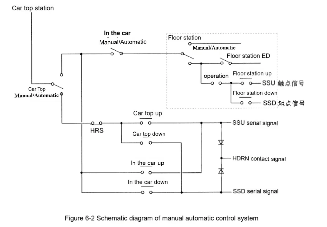
The technical key points of manual automatic control are mainly reflected in the control priority of car top → car interior → control cabinet (or HIP). The control principle is to switch the power supply of "up and down" line switches at all levels through manual/automatic switches to achieve the purpose of priority control. For example, if the manual automatic switch on the car top is turned to the "manual" side, only the "up and down" line buttons on the car top have power, while the up and down buttons in the car and control cabinet (HIP) have no power.
In addition, in addition to giving the control system an operating instruction, the "up and down" line signals at all levels will also form a manual "confirmation" signal "HDRN". This signal must be valid at the same time as the "up and down" line signal before the elevator can be manually started.
The schematic diagram of the manual automatic control system using the ELENESSA (VFGL/VFGLC) elevator as an example is as follows:
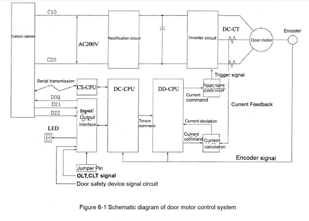
The door machine control system is relatively complex, but it can be understood by comparing it to the control cabinet. For example, the door photoelectric switch and car door lock signal are equivalent to the function of the shaft terminal switch. The door machine, synchronous belt, etc. are equivalent to the traction system composed of the traction machine and the wire rope. The inverter, DC-CT, etc. of the control cabinet are integrated on the door machine printed board.
From the control point of view, the door movement control is also divided into the control part and the drive part, and parameter setting is required, similar to the control cabinet setting of the motor, acceleration, speed and other parameters. If these door machine parameters are not set correctly, it is easy to cause the door machine to run slowly, similar to the elevator car running slowly and automatically to find the leveling position.
In addition, the elevator has torque protection measures such as stalling and blocking, and there are similar protection measures in the door machine control. If the setting is improper, it is easy to cause the door motor to overheat and other situations.
Due to the complexity of the door machine system, the detailed principles of the components involved are unfolded in general steps.
The schematic diagram of the door machine control system is shown below:
6.2. General steps:
6.2.1. Car top manual automatic operation
6.2.1.1. After the up and down buttons are pressed, it does not start.
The general steps for inspection are to check the fault display and various status LEDs on the car top station and P1 board before the elevator starts, such as #29. If there is a fault code or the status LEDs are abnormal, refer to other chapters in the "Troubleshooting Manual" to troubleshoot the fault according to the actual situation. Next, first check whether the signal voltage of each level is normal according to the priority principle in the overview section, and ensure that the "HDRN" signal is normal. Finally, since the "HDRN" signal is normal, it is necessary to check whether the "up and down" line number has been transmitted to the P1 board. Since the "up and down" line signals on the car top and in the car are transmitted serially, which is different from the signals in the control cabinet and HIP, it is necessary to check whether the communication (CS) of the car is normal. For this part, please refer to the OR system chapter.
6.2.2. Door motor operation failure
The door machine system is relatively complex, and the fault phenomenon and cause present a many-to-many relationship. Troubleshooting should be carried out based on the door machine components.
6.2.2.1. Door motor encoder
The door motor encoder is divided into two types: asynchronous door motor encoder and synchronous door motor encoder. The asynchronous door motor encoder signal is relatively simple, as long as the A/B phase signal is consistent with the wiring phase sequence in the power cable. If it is connected in reverse, it may cause overcurrent, reversal and other faults.
The synchronous door motor encoder line is more complicated. In addition to the asynchronous door motor encoder signal, it also includes a phase confirmation signal. And the magnetic pole position in the synchronous door motor is fixed, so any signal in the encoder has a problem, which can easily cause the door motor to run jitter, abnormal heating or powerless to open the door, etc., which may damage the door motor in severe cases.
6.2.2.2. Door motor power cable
Although the power cable has only three wires, the wiring is distinguished by phase sequence. No matter what kind of wiring, the phase sequence has only two differences: forward or reverse. Just reverse once. If the problem cannot be solved, you need to check whether there are problems with other components. If the phase sequence is wrong, the door motor may shake violently or fail to open and close the door.
If one phase of the power cable is poorly connected, the torque vector space rotation trajectory is elliptical due to the lack of phase, and the door motor will vibrate violently.
If two phases of the power cable are poorly connected, the three phases cannot form a loop, and the door motor failure phenomenon is the same as the three-phase cable is not connected.
6.2.3. Door opening and closing position switch
Regardless of the type of door motor, the final door opening and closing position signal is CLT and OLT. If these two signals are missing, the door motor may run abnormally, or a fault code may appear on the P1 board, and the elevator will enter a state where it can no longer be started. It should be noted that the OLT signal does not have a direct photoelectric signal in some door motor configurations, but is combined into CLT and OLT signals through the car door lock (41G) and CLT photoelectric signal. The specific rules are as follows:
1) When the CLT signal for control is valid when both 41G and CLT signals are valid.
2) When the OLT signal for control is only CLT signal, but no 41G signal, it is valid.
Note: In the absence of OLT photoelectric configuration, the OLT jumper must be short-circuited
The OLT and CLT signals indicate the door's fully opened and fully closed states, while the 41DG signal also indicates the door's closed and opened states. If the two are inconsistent, the elevator will find such fault states through logical relationship matching. However, the 41DG signal is generally used as the standard, so the literal meaning of the fault code mostly points to CLT and OLT faults, but when checking the fault, you should also pay attention to whether the 41DG signal is abnormal.
6.2.4. Light curtain and safety touch panel
The light curtain and safety touch panel are used to protect passengers from being hit by the car door when entering and exiting the car. The signal of the safety touch panel is valid without time limit. As long as the signal is activated, the door will remain open. However, the light curtain signal has a time limit to prevent smoke and other obstructions. If the time limit is exceeded, the car door will be forcibly closed. Therefore, the contacts of the light curtain and the contacts of the safety touch panel cannot be short-circuited. Short-circuiting will cause unsafe hidden dangers such as fire.
In addition, if the car door is closed, the signals of the light curtain and the safety touch panel cannot be activated. At this time, if the contacts are activated, the elevator may open the brake but not start.
6.2.5. D21/22 signal
The door motor's action command for opening or closing the door is completely dependent on the D21/D22 signal, which is transmitted via a dedicated line in the accompanying cable. If the door motor does not open or close the door, in addition to checking the signals around the car top station and the door machine itself, you should first check whether the door opening and closing signals transmitted by the control cabinet are normal. If the door opening and closing signals are abnormal, you need to use the fault code of the control cabinet and other means to determine the cause of the fault.
6.2.6. Crossover settings
The crossover settings of the door motor are divided into 3 groups.
1) Basic type and parameter settings of the door motor, such as door type, door opening width, torque protection margin and control mode (synchronous/asynchronous motor). Common fault phenomena include incorrect door type settings, causing door motor vibration; incorrect door opening width settings, causing slow door opening and closing to learn door width; incorrect torque protection margin settings, causing door motor stalling and overheating; incorrect control mode settings, causing overcurrent protection during door motor operation.
2) Door opening settings, such as acceleration and deceleration, terminal speed and deceleration position, etc., improper settings may cause collision when the door is in place.
3) Door closing settings, similar to door opening settings, if improper settings, there will be collision when the door is in place, or the speed of the final stage of door closing is too slow and the hall door cannot be closed.
6.2.7. Door closing holding torque
When the door is fully closed, the size of the door gap will be determined based on the position of the car door lock and the CLT signal (such as the situation where the passenger's clothes are caught). If the door gap is large, the door closing holding torque applied is also large. If the door motor consistently applies a large door closing holding torque due to poor position adjustment, the door motor will be overloaded.
Note: If the door machine system fails, the corresponding fault code will generally be displayed on the 7SEG of the car top station for maintenance personnel to check. The specific door machine fault code and fault phenomenon can be referred to the following table:
| 7-segment LEDs display | Fault explanation | Remark |
| 0 | Communication transmission abnormality (DC↔CS) | When communication is abnormal, the communication CS-CPU resets once every 1 second, and the door motor runs at a slow speed after emergency stop. It returns to normal after the fault disappears. |
| 1 | IPM Comprehensive Fault | The base trigger signal is cut off and the door motor stops suddenly. It can be restored after the fault disappears. |
| 2 | DC+12V overvoltage | The base trigger signal is cut off, the door motor stops suddenly, and the DC-CPU is reset. It returns to normal after the fault disappears. |
| 3 | Main circuit undervoltage | The base trigger signal is cut off and the door motor stops suddenly. It returns to normal after the fault disappears. |
| 4 | DC-CPU WDT abnormality | The base trigger signal is cut off and the door motor stops suddenly. It returns to normal after the fault disappears. |
| 5 | DC+5V voltage abnormality | The base trigger signal is cut off, the door motor stops suddenly, and the DC-CPU is reset. It returns to normal after the fault disappears. |
| 6 | Initialization state | The door motor system self-detects and the base trigger signal is cut off. |
| 7 | Door switch logic abnormality | The door circuit action is cut off and cannot return to normal after the fault disappears. |
| 8 | ||
| 9 | Abnormal door opening and closing direction | The door circuit action is cut off and cannot return to normal after the fault disappears. |
| A | Over rated speed | After the door motor stops suddenly, the door will open and close slowly. |
| B | ||
| C | Door motor overheating (synchronous door motor) | After the door motor stops suddenly, the door will open and close slowly. If the temperature returns to normal, the door motor can be restored. |
| D | Overload | After the door motor stops suddenly, the door will open and close slowly. If the temperature returns to normal, the door motor can be restored. |
| E | ||
| F | Too high speed | After the door motor stops suddenly, the door will open and close slowly. |
| 0. | ||
| 1. | ||
| 2. | ||
| 3. | ||
| 4. | GS signal abnormality | After the door motor stops suddenly, the door will open and close slowly. It will return to normal after the door is fully closed. |
| 5. | Position detection abnormality | After the door motor stops suddenly, the door will open and close slowly. It will return to normal after the door is fully closed. |
| 6. | (Warning fault) | |
| 7. | ||
| 8. | ||
| 9. | Phase Z fault | Encoder Z phase fault detection for 16 times in a row, slow door opening and closing [A1] |
| A. | Position counting area check | After the door motor stops suddenly, the door will open and close slowly. It will return to normal after the door is fully closed. |
| B. | OLT position detection abnormality | After the door motor stops suddenly, the door will open and close slowly. It will return to normal after the door is fully closed. |
| C. | Encoder abnormality | The elevator stops at the nearest floor and stops the door motor after the door is fully closed. The elevator runs normally after the fault is eliminated. |
| D. | DOOR-CUT | Normal state. |
| E. | DLD protection action | When the protection value is reached, the door motor will immediately run in the reverse direction. *1 |
| F. | Normal working status | Normal working status |
6.3. Common faults
6.3.1. Fault phenomenon: The car door cannot be closed
Possible causes and countermeasures of the fault:
1) Cause 1: Abnormal D21, D22 signal cables
Countermeasures: Check whether the D21, D22 signal cables are connected correctly and normally.
2) Cause 2: Door photoelectric size adjustment error
Countermeasures: Check the door photoelectric size.
3) Cause 3: Door machine board cross pin error
Countermeasures: Check the door machine board cross pin according to the 531 drawing.
4) Cause 4: Abnormal action of MBS or safety touch panel
Countermeasures: Check whether the MBS cable is connected correctly, whether the light curtain and light curtain control box are intact; whether the safety touch panel mechanical adjustment is correct, and whether the micro switch is sticky.
5) Cause 5: Component damage
Countermeasures: Check whether the components related to opening and closing the door are intact, including the door motor, door machine board, door machine drive unit, door closing button, etc.
6.3.2. Fault phenomenon: abnormal door opening and closing speed
Possible causes and countermeasures of the fault:
1) Cause 1: Door machine board cross-pin error
Countermeasure: Check the door machine board cross-pin according to the 531 drawing.
2) Cause 2: Door motor hardware failure
Countermeasure: Replace the door motor.
3) Cause 3: Abnormal encoder signal
Countermeasure: Replace the encoder and check whether the encoder cable is interfered.
4) Cause 4: Door photoelectric size adjustment error
Countermeasure: Re-adjust the door photoelectric size.
5) Cause 5: Printing board failure
Countermeasure: Replace the door machine board and the door machine drive unit printing board.
7. Communication circuit (OR)
7.1. Overview
The OR part on the wiring diagram mainly includes the communication circuit.
Because the types of elevators are different, the communication distances and contents are different, so many communication protocols are used. They can be roughly divided into two categories, the communication system based on the CAN standard protocol and the communication system based on the RS series communication protocol. Although the various communication protocols are quite different. But for on-site troubleshooting, the main focus should be on ensuring that the line is good. Therefore, you should have a certain understanding of the basic circuit.
7.1.1. CAN system
The CAN system is a bus structure. Each node uses a unified power supply (+12V GND) and a "one" data line. This data line uses high and low levels to distinguish "0" and "1". Each node uses the "listening" method to receive data on the data line at the same time, and then determines whether to process the message based on the message ID number. When sending, all nodes also send ID numbers to the line at the same time. Due to the electrical characteristics of the CAN line, one of the high and low levels is a "dominant" level and the other is a "hidden" level. When two nodes send "dominant" and "hidden" levels to the data line at the same time, the data line is a "dominant" level. In the ID number of a high-priority node, the "dominant" level has a greater weight, so when a low-priority node hears that a high-priority node is sending a message, it will stop sending its own message and wait for the next message cycle to try to send again.
Because of the listening and "visible/hidden" levels, although there is only one data line, it can send and receive at the same time, which improves the efficiency of the line. However, in order to improve the ability to resist common-mode interference, the level on the data line is transmitted in a differential manner, so there are the so-called "CANH" and "CANL".
In short, the CAN communication line is composed of power and data lines, each with two lines, and the line is in the form of twisted pair wiring.
7.1.2. RS system
The communication protocol of the RS series is relatively traditional, with a data receiving line "RxD", a data sending line "TxD", and a grounding line "GND".
In terms of anti-interference measures, the power supply and data lines are also in the form of twisted pairs, just like the CAN system.
7.1.3. Elevator communication system
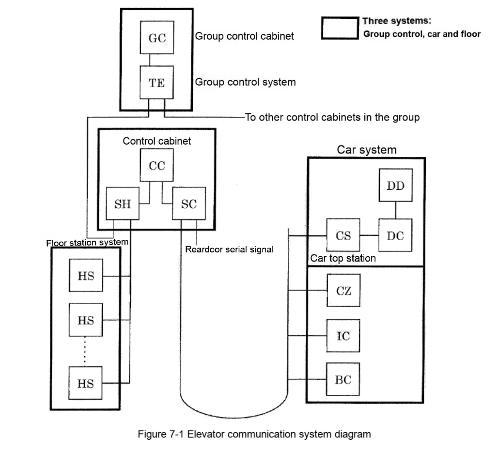
According to the bus, elevator communication can be divided into four parts: group control side, car side, floor station side and other auxiliary functions. Each part takes the P1 board as the starting node and is arranged in a bus manner. Any "star" or "forked" connection is wrong. A dedicated power supply is required for each bus. Especially for the floor station side bus, since the number of nodes is far more than other buses, it is necessary to add a "floor station power supply box" according to the number of floor stations to maintain the voltage balance and power balance of the power supply on the entire bus.
In addition, when the number of floors reaches a certain level, H10-H20 cannot bear the load, and an additional transformer will be added to provide another power supply - H20A and H20A. At this time, the floor power load needs to be distributed and balanced between the two power supplies.
The schematic diagram of the elevator communication system is as follows:
7.2. General steps
Communication failures manifest themselves in a variety of phenomena that cannot be listed one by one. However, following certain inspection steps and sequences can, to a certain extent, clarify ideas during the inspection process, laying the foundation for narrowing the scope and determining the cause of the fault.
7.2.1. Determine which communication bus has a problem based on the P1 board fault code
Both new and old elevators have communication fault codes, the difference is the level of detail. However, even if a large fault code is used, it can be distinguished which bus has a problem.
Furthermore, many signals are transmitted through communication. Once a communication failure occurs, the malfunction of many signals will cause the superposition of various elevator fault phenomena. If the interface signal line is checked directly, it is likely to be ineffective.
7.2.2. Check whether the power supply and data line of the faulty communication line are normal
Since the communication system uses a bus, a good line is the cornerstone of normal communication operation. Confirming whether the line is good is not simply a matter of checking whether it is on or off. You need to check:
1) Is the continuity good?
For communication lines that are too long, spare lines can be used to form a loop and then measured together.
2) Is the insulation resistance of the cable good?
Since the communication line transmits high-frequency signals, if the insulation is poor, although there is no direct short circuit, the high-frequency signal will still have a short circuit phenomenon similar to the low-frequency signal.
3) Is the twist pitch of the twisted pair on the communication line normal?
At present, all communication lines in the production elevators basically use twisted pair to improve the anti-interference of the transmission signal. When using twisted pair, there is a problem of "twist pitch" (twist pitch refers to the length of the twisted pair twisted around each other). The length of the twist pitch is related to the wavelength of the electromagnetic wave to be resisted. The interference frequency with a wavelength significantly greater than the twist pitch cannot have a significant impact on the signal on the line. Therefore, the use of non-standard twist pitch cables to replace the original communication line at will, even if it is only a very small section, will have an adverse effect on the normal transmission of the signal on the line, not to mention ordinary cables.
7.2.3. Determine which node has a problem by the status LEDs on the communication board of each node
7.2.4. Check the setting switch and terminal resistance of each node
The messages received and sent by each node have their own ID number, which is determined by the floor setting, front and back door settings, etc. If the setting switch is set incorrectly, it may cause a conflict or cause the message to be discarded due to incorrect ID.
The physical meaning of the terminal resistance is that the bus line is long, and the signal pulse time is extremely short. There is a certain time difference in the transmission of the signal on the line. The terminal resistance is a necessary measure to prevent signal reflection. Therefore, the terminal resistance is connected to the "farthest node currently in use." If the farthest node changes, the terminal resistance needs to be reconnected.
7.2.5. Problems other than the above inspection measures
1) The communication program version of each node, especially the layer station node, must be consistent.
2) For some special layer station nodes, the hardware (printing board) version must be consistent.
3) Check whether the AC power supply, such as lighting, has an impact on communication.
7.3. Common Faults
7.3.1. Fault phenomenon: The floor buttons in the car cannot be registered
Possible causes and countermeasures of the fault:
1) Reason 1: The serial signal cable is abnormal.
Countermeasure: Check whether the serial cable from the car control box to the car top station and from the car top station to the control panel is short-circuited, broken, or wrongly connected.
2) Reason 2: The control box printed board is set incorrectly.
Countermeasure: Check the jumper pin and potentiometer settings according to the drawing.
3) Reason 3: The elevator enters the fire protection, elevator lock and other operation modes.
Countermeasure: Check whether the fire protection and elevator lock are in action.
4) Reason 4: Printed board failure.
Countermeasure: Replace the serial-related printed boards in the car: P1 board, door machine board, BC board in the car, control box power supply, etc.
7.3.2. Fault phenomenon: The hall call button cannot be registered
Possible causes and countermeasures of the fault:
1) Reason 1: Serial signal cable is abnormal.
Countermeasures: Check whether the serial cable from the hall call to the floor station and from the floor station to the control panel is short-circuited, broken, or connected incorrectly.
2) Reason 2: The elevator is out of group control, and the group control is abnormal.
Countermeasures:
▲ Check the connection cable between the single elevator and the group control.
▲ Check the cross-pin setting of the P1 board. Whether the P1 board matches the elevator number.
▲ Check whether the P1 board and the group control GP1, GT1 printing boards are normal.
▲ When there is an OEPS function, confirm whether the setting is valid.
3) Reason 3: The floor potentiometer is set incorrectly.
Countermeasures: Adjust the FL1, FL0 settings according to the drawing.
4) Reason 4: Printing board failure.
Countermeasures: Replace the external call serial related printing boards: external call printing board, floor station printing board, P1 board, group control board, etc.
7.3.3. Fault phenomenon: The internal and external calls are automatically cancelled when the elevator is running
Possible causes and countermeasures of the fault:
1) Reason 1: Signal interference
Countermeasures:
▲ Check whether each grounding wire is properly grounded.
▲ Try to avoid parallel and close routing of serial lines and strong power cables.
▲ Ground the spare line in the flat cable.
▲ Take anti-interference measures according to the actual situation on site.
2) Reason 2: Printed board failure.
Countermeasures: Replace the serial-related printed board.


