
1. Product Introduction
1.1 Product Overview
The elevator multi-party communication system is an important part of the elevator, and mainly provides the following functions:
① In the event of an emergency in the elevator, trapped people can use the system to alert the rescue service organization or the monitoring room;
② During installation and maintenance, staff in various operating areas of the elevator can use the system to communicate with each other.
1.2 Product standards and specifications
DigTel elevator multi-party communication system complies with the following standards for elevator multi-party communication system requirements:
①GB 7588.1 Safety Specifications for Elevator Manufacturing and Installation
②GB/T 24475-2009 Requirements for Elevator Remote Alarm Systems
③GB/T 24477-2009 Additional Requirements for Elevators for People with Disabilities
④GB 26465-2011 Safety Specifications for Fire Elevator Manufacturing and Installation
1.3 Main features
DigTel elevator multi-party call system uses digital technology and has the following advantages:
① Clear voice call quality
② Good anti-interference ability
③ Advanced data transmission network
④ Free network topology
⑤ Optimized echo suppression technology
⑥ Full expansion capability
1.4 Transmission network
The transmission network of the DigTel elevator multi-party communication system is divided into an intranet and an extranet.
① The intranet bus is used to connect the control cabinet communication device with the elevator car, car top and pit communication devices.
⑴ Topology: free topology.
⑵ Transmission distance: 500m.
⑶ Cable specification: 2*0.75mm2, non-twisted pair, no shielding layer.
② The extranet bus is used to connect the monitoring room communication device with each control cabinet communication device.
⑴ Topology: free topology.
⑵ Networking distance: The transmission distance from the monitoring room to the farthest elevator control cabinet communication device is 3000m.
⑶ Cable specification: 60227 IEC 53 (RVV) non-shielded 2*0.75mm2.
1.5 Definition
①Installation mode
Installation mode is used in the installation phase of the elevator. At this time, the external network has not been connected, and the monitoring room Intercom device cannot receive alarm requests. In this mode, only the intercom function can be used, and the remote alarm function is not enabled.
②Alarm filtering
According to the requirements of GB/T 24475-2009, when the elevator is in any of the following situations, the alarm should be cancelled by filtering.
--The car is in the unlocking area, and the car door and floor are fully open;
--During the operation of the car and the opening of the door to the next floor station.
③Alarm termination
According to the requirements of GB/T 24475-2009, it is a message sent by the alarm system to the rescue service organization to notify that the trapped state has ended.
④Broadcast
The monitoring room intercom device broadcasts voice to all intercom devices in the specified area at the same time.
⑤Emergency power supply capacity detection function
According to the requirements of GB/T 24475-2009, when the capacity of the emergency power supply is less than the capacity required for the normal operation of the alarm system for 1 hour, measures should be taken to immediately and automatically notify the rescue service organization of the situation.
⑥Rescue service organization
According to the requirements of GB/T 24475-2009, it is an organization responsible for receiving alarm information and rescuing users trapped in the equipment.
⑦Daily mode
Daily mode refers to the situation where the elevator has been put into normal use. At this time, the external network is connected and in normal communication state. In this mode, the call system can provide elevator call and remote alarm functions.
⑧Elevator call
The communication request initiated by the staff in each working area of the elevator (such as the machine room, car, car top, pit, emergency and test operation screen side) in order to collaborate to complete a task.
⑨ID of call device
Each call device in the call system has a unique number to identify the location of the call device. The ID number consists of four digits.
⑩Remote alarm
When an emergency occurs in the elevator (such as power outage, malfunction, etc.), the trapped personnel (usually passengers in the car, or staff on the top of the car or in the pit) initiate the process of requesting rescue by pressing the alarm trigger button.
2. Basic structure of DigTel elevator multi-party communication system
2.1 Composition
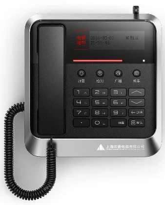
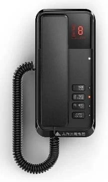
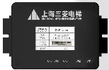
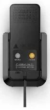
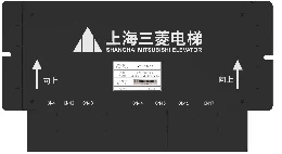
The appearance of each communication device in the DigTel elevator multi-party communication system is shown in Table 1, and the configuration quantity is shown in Table 2.
Table 1 Overview of the communication device appearance
| Monitoring room intercom
| Control cabinet intercom device
For machine room elevator | Car intercom device
|
| Car top/pit communication device
| Control cabinet communication box
For Machine roomless elevator | ETP call operation device
For Machine roomless elevator |
| Table 2 Configuration Quantity | |||
| Number | Part Name | Quantity | Remark |
| 01 | Monitoring room intercom device | 1 unit/system | |
| 02 | Control cabinet intercom device | 1 unit/elevator | For machine room |
| 03 | Car intercom device | 1 unit/elevator | |
| 04 | Car top intercom device | 1 unit/elevator | |
| 05 | Pit intercom device | 1 unit/elevator | |
| 06 | Control cabinet intercom box | 1 unit/elevator | For machine roomless |
| 07 | ETP intercom operating device | 1 unit/elevator | For machine roomless |
2.2 System connection
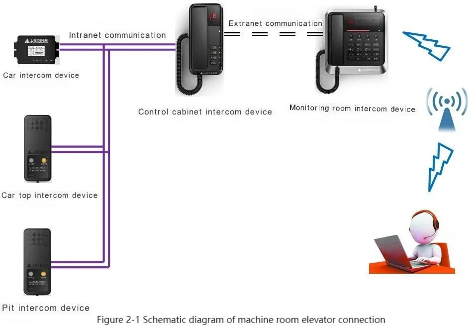
The communication devices in the elevator car, car top, pit and control cabinet are connected through the intranet bus. The communication device in the control cabinet is connected to the communication device in the monitoring room through the extranet bus. Each communication device in the monitoring room can connect 256 elevators.
The remote alarm signal sent by the communication device in the car, car top or pit is sent to the rescue service organization through the mobile communication network by the alarm module in the communication device in the monitoring room (this function is optional in the contract).
Figure 2-1 is a schematic diagram of the connection of the machine room elevator.
The system wiring diagram is in the random factory drawing book of the elevator. The applicable scope of each drawing number is as follows:
①P246014B000 Applicable to machine room-less elevators of independent technology ladder, including:
LEHY-MRL, LEHY-MRL-G;
LEHY-MRL-II.
②P246015B000 Applicable to machine room-less elevators of independent technology ladder (except LEGY-II), including:
LEGY;
LEHY-III, LEHY-IIIW, LEHY-IIIB, LEHY-III-S;
LEHY-M-II;
LEHY-H;
HOPE-IIG, CIC-V;
NexWay-CR.
③P246016B000 Applicable to machine room-less elevators of imported technology ladder, including:
ELENESSA;
MAXIEZ-LZ.
④P246017B000 is applicable to machine room elevators with imported technology, including:
NexWay-S, NexWay-B;
NexWay;
NEXIEZ-MR;
MAXIEZ-CZ, MAXIEZ-M, MAXIEZ-H, MAXIEZ-B.
⑤P246018B000 is applicable to LEGY-II elevators.
2.3 How to use the communication device
2.3.1. Car communication device
2.3.1.1. Signal connection
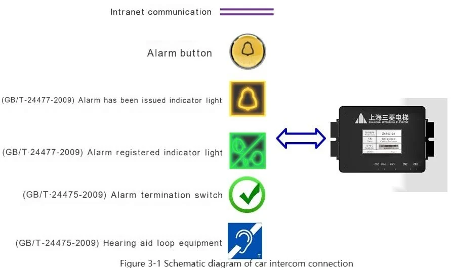
The connection diagram of the car intercom device is shown in Figure 3-1.
2.3.1.2 Operation in installation mode
2.3.1.2.1 Inter-elevator communication
a) Initiate a call
① When the "Alarm" button is pressed, the call device will broadcast a prompt voice: "Installation mode. Please keep pressing the alarm button and enter the elevator call after 10 seconds"
② Keep pressing the "Alarm" button on the control box for 10 seconds to initiate a call request.
b) Answer a call
① Call request initiated by the control cabinet call device or the monitoring room call device: directly connected.
② Call request initiated by the car top or pit call device: this call device will emit a receiving prompt tone. Keep pressing the "Alarm" button on the control box for 10 seconds to answer the call.
c) End a call
① Keep pressing the "Alarm" button for 10 seconds to end the call.
② Call with the control cabinet call device: hang up by the control cabinet call device.
③ Call with the car top or pit call device: the call ends automatically after 10 minutes.
2.3.1.3 Operation in daily mode
2.3.1.3.1 Remote alarm
The communication system determines whether the alarm triggered by the car communication device should be filtered based on the operating status signal input by the elevator control system.
2.3.1.3.1.1 When the alarm is not filtered
a) Triggering an alarm
▲ Press the "Alarm" button on the control box to send an alarm signal to the rescue service organization through the monitoring room communication device. At the same time, a three-way call can be made with the monitoring room communication device.
▲ While pressing the alarm button, the "Alarm has been issued indicator light" on the control box flashes.
▲ When the monitoring room communication device successfully sends the alarm signal, the "Alarm has been issued indicator light" lights up.
b) Establishing a call
▲ When the rescue service organization answers the call, the call is established.
▲ At the same time, the "Alarm has been registered indicator light" lights up.
c) Ending a call
① Only the rescue service organization can hang up.
d) Terminating an alarm
▲ When the rescuer completes the rescue, press the "Alarm Termination" switch in the control box sub-door, and the rescue service organization will be notified through the monitoring room communication device that the rescue is completed. At the same time, the "Alarm has been issued indicator light" signal and the "Alarm has been registered indicator light" go out.
2.3.1.3.1.2 In the alarm filtering state
a) Trigger the alarm
▲ Press the "Alarm" button on the control box, no alarm signal is issued, and only the communication device in the monitoring room can be used for communication.
b) Establish a call
▲ After the communication device in the monitoring room answers, the call is established.
c) End the call
▲ The communication device in the monitoring room hangs up.
2.3.1.3.2 In-elevator conversation
a) Initiate a conversation
▲ Press the "Alarm" button on the control box for 10 seconds to initiate a conversation request.
b) Answer a conversation
▲ A conversation request initiated by the control cabinet conversation device or the monitoring room conversation device: connect directly.
▲ A conversation request initiated by the car top or pit conversation device: this conversation device will emit a prompt tone for answering. Press the "Alarm" button on the control box for 10 seconds to answer the conversation.
c) End a conversation
▲ Press the "Alarm" button for 10 seconds to end the conversation.
▲ A conversation with the control cabinet conversation device: hang up by the control cabinet conversation device.
▲ A conversation with the car top or pit conversation device: the conversation ends automatically after 10 minutes.
2.3.1.3.3 Other functions
The car intercom device can be connected to an external hearing aid loop device to provide hearing-impaired people with the ability to receive sound in the T-mode of the hearing aid.
2.3.2 Car top and pit communication device
2.3.2.1 Signal connection
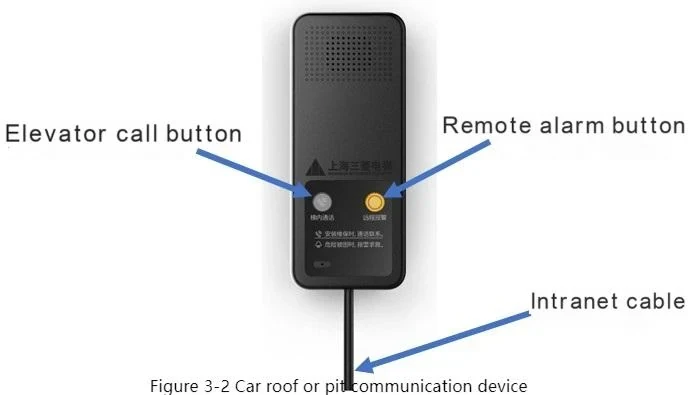
The car top or pit communication device is connected to the control cabinet communication device through the intranet, as shown in Figure 3-2.
2.3.2.2 Operation in installation mode
2.3.2.2.1 Inter-elevator call
a) Initiate a call
▲Press the "Inter-elevator call" button to initiate a call request.
▲Press the "Remote alarm" button, and the call device will broadcast a prompt voice: "Installation mode. Please continue to press the alarm button and enter the inter-elevator call after 10 seconds."
b) Answer a call
▲Call request initiated by the control cabinet call device or the monitoring room call device: directly connected.
▲Call request initiated by the car, car top or pit call device: this call device will issue a receiving prompt tone. Press the "Inter-elevator call" button to answer.
c) End a call
▲Press the "Inter-elevator call" button to end the call.
▲Call with the control cabinet call device: the control cabinet call device hangs up.
▲Call with the car, car top or pit call device: the call ends automatically after 10 minutes.
2.3.2.2.2 Operation in daily mode
2.3.2.2.1 Remote alarm
a) Trigger alarm
▲ Press the "Remote alarm" button to send an alarm signal to the rescue service organization through the monitoring room intercom. At the same time, a three-way call can be made with the monitoring room intercom.
b) Establish a call
▲ When the rescue service organization answers the call, the call is established
c) End the call
▲ The call can only be terminated by the rescue service organization.
2.3.2.2.1 Inter-elevator talk
a) Initiate a call
▲ Press the "Inter-elevator talk" button to initiate a call request.
b) Answer a call
▲ A call request initiated by the control cabinet talk device or the monitoring room talk device: directly connected.
▲ A call request initiated by the car, car top or pit talk device: this talk device will emit a listening prompt tone. Press the "Inter-elevator talk" button to answer.
c) End a call
▲ Press the "Inter-elevator talk" button to end a call.
▲ A call with the control cabinet talk device: hung up by the control cabinet talk device.
▲ A call with the car, car top or pit talk device: the call ends automatically after 10 minutes.
2.3.3 Control cabinet intercom device (for elevators with machine room)
2.3.3.1 Signal connection
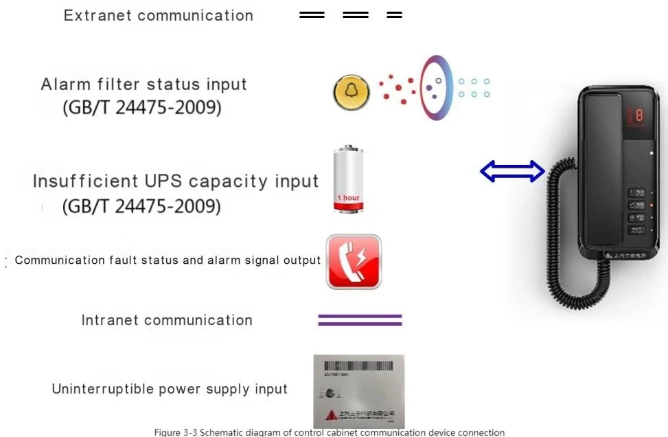
The connection diagram of the control cabinet intercom device is shown in Figure 3-3.
2.3.3.2 Operation in installation mode
2.3.3.2.1 Inter-elevator call
a) Initiate a call
▲ Pick up the handset and press the "1" key to talk directly to the elevator car intercom device. After communication is established, the indicator light next to the button flashes.
▲ Pick up the handset and press the "2" key to talk directly to the elevator car top intercom device. After communication is established, the indicator light next to the button flashes.
▲ Pick up the handset and press the "3" key to talk directly to the elevator pit intercom device. After communication is established, the indicator light next to the button flashes.
b) Answer a call
▲ When a call request is initiated by the elevator car, car top or pit intercom device, this intercom device will emit an answering prompt tone, and the number of the corresponding intercom device will be displayed on the display window.
▲ Pick up the handset and press the button with the corresponding number to answer the call. After communication is established, the light next to the button flashes.
c) End a call
▲ Put the handset back to the base to hang up the call.
2.3.3.2.2 Registration function of slave communication device
2.3.3.2.2.1 Application occasion
Because early elevators may not have pit and car top communication devices installed. The communication system will detect communication failures of car top and pit communication devices during detection. To deal with such situations, the registration function of the control cabinet communication device can be used to set whether the car, car top and pit communication devices are installed.
2.3.3.2.2.2 Instructions
① While the control cabinet intercom device is powered on, press and hold the 1 key. The display window displays 1 to enter the installation registration mode. The factory default is that the car, car top, and pit intercom devices are all registered and installed.
② After entering the installation registration mode
▲ The indicator light next to the 1 key is on. Press the 1 key to set whether the car intercom device is registered and installed. Each time the key is pressed, the display window displays "1" or "0" in a cycle. 1 means registered installation, and 0 means not registered installation.
▲ Press the 2 key to set whether the car top is registered and installed. Each time the key is pressed, the display window displays "1" or "0" in a cycle. 1 means registered installation, and 0 means not registered installation.
▲ Press the 3 key to set whether the pit is registered and installed. Each time the key is pressed, the display window displays "1" or "0" in a cycle. 1 means registered installation, and 0 means not registered installation.
③ Press the "Monitoring Room" key to view the registration and installation setting results.
④ After the settings are completed, power off and restart the control cabinet communication device to save the settings.
2.3.3.3 Operation in daily mode
2.3.3.3.1 Control cabinet ID
2.3.3.3.1.1 ID description
▲ID Rules
In the intercom system, the ID of each intercom device is a unique four-digit number. The thousands, hundreds and ones digits are set by the intercom device in the control cabinet, and the ones digit is determined by the type of intercom device, see Table 3.
| Table 3 Description of the ID digit | |
| Intercom type | The single digit of ID |
| Control cabinet intercom device | 0 |
| Car intercom device | 1 |
| Car top intercom device | 2 |
| Pit intercom device | 3 |
For example: ID=3451 indicates the car intercom device.
▲ID=001
Set the control cabinet intercom device ID to "001" and then pick up the handset. This operation is equivalent to flipping the alarm termination switch. At this time, the alarm termination signal will be sent to the rescue service organization through the monitoring room intercom. At the same time, the "alarm has been issued indicator light" signal and the "alarm has been registered indicator light" on the control box go out.
▲ID=002
The factory default value of the control cabinet intercom device ID is "002", which is in installation mode.
▲ID=003~999
When the intercom system is put into normal use, please set the control cabinet intercom device ID to "003~999". At this time, the installation mode will be exited and the daily mode will be entered.
2.3.3.3.1.2 ID Setting
The ID of the control cabinet intercom device must be set when the external network communication is normal and the control cabinet intercom device is in standby.
The setting method is as follows:
▲ Thousands digit: long press the "1" key, the display window will display the numbers "0~9" in a loop. When the display window displays the number you want to select, release the "1" key, and the number will be set as the thousands digit in the ID.
▲ Hundreds digit: long press the "2" key, the display window will display the numbers "0~9" in a loop. When the display window displays the number you want to select, release the "2" key, and the number will be set as the hundreds digit in the ID.
▲ Tens digit: long press the "3" key, the display window will display the numbers "0~9" in a loop. When the display window displays the number you want to select, release the "3" key, and the number will be set as the tens digit in the ID.
▲ After the three-digit number is set, long press the "Monitoring Room" key, and the display window will display the set ID.
▲ When the microphone is lifted, the control cabinet intercom device will upload the ID number to the monitoring room intercom device. After the upload is successful, the display window will show "1". If the display window shows "0", it means that the ID already exists, the upload is unsuccessful, and the ID must be reset.
▲ Complete the setting after power off and restart.
Note: Only after the phone ID is set according to the above operation and saved in the monitoring room communication device, the elevator room, car, car top, and pit communication devices can communicate with the monitoring room communication device.
2.3.3.3.2 Inter-elevator conversation
Same as inter-elevator communication in installation mode, see 2.3.3.2.1.
2.3.3.3.3 Slave intercom device registration function
Same as the registration function of the slave intercom in installation mode, see 2.3.3.2.2.
2.3.3.3.4 Talk to the monitoring room
a) Initiate a call
▲ Pick up the handset and press the "Monitoring Room" button. After communication is established, the indicator light next to the button flashes.
b) Answer a call
▲ When the monitoring room intercom device initiates a call request, this intercom device will emit an answering prompt tone, and the number "6" of the corresponding intercom device will be displayed on the display window.
▲ Pick up the handset and press the "Monitoring Room" button to answer the call. After communication is established, the light next to the button flashes.
c) End a call
▲ Put the microphone of this machine back to the base to hang up the call.
▲ Put the microphone of the monitoring room intercom device back to the base to hang up the call.
2.3.3.3.5 Alarm when emergency power supply capacity is insufficient
When the "emergency power supply capacity insufficient signal" is valid, the control cabinet intercom will send an alarm signal to the rescue service organization through the monitoring room intercom.
2.3.3.3.6 Alarm Filtering
The alarm filter signal is output by the elevator control system according to the elevator's operating status:
▲ When the "alarm filter signal" input contact is closed, the alarm initiated by the car intercom device is filtered.
▲ When the "alarm filter signal" input contact is open, the alarm initiated by the car intercom device is not filtered.
2.3.3.3.7 Communication Failure Status and Alarm Signals
The communication failure state and alarm signal are a combined output signal. In the following cases, the state of the signal contact changes as follows:
Closed once every 27 seconds, the closing time is 3 seconds:
▲ When the communication between this communication device and the car, car top and pit communication device fails;
▲ When the communication between this communication device and the monitoring room communication device fails;
▲ When the communication between the monitoring room communication device and the rescue service organization fails.
When the alarm button is pressed on the car, car top and pit communication device, the contact closes for 5 seconds.
2.3.4 Monitoring room communication device
2.3.4.1 System connection
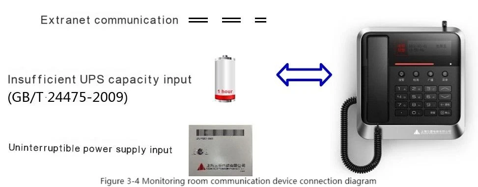
See Figure 3-4 for the connection diagram of the monitoring room communication device.
2.3.4.2 Basic operations and functions
2.3.4.2.1 Monitoring room communication device with mobile communication module (optional in the contract)
2.3.4.2.1.1 Communication
a) Initiate a call
You can initiate a call to any communication device in the system. The operation is as follows:
▲ If you want to talk to the car communication device with ID 111, pick up the microphone and press "1111" to talk to the communication device;
▲ If you want to talk to the car top communication device with ID 111, pick up the microphone and press "1112" to talk to the communication device;
▲ If you want to talk to the pit communication device with ID 111, pick up the microphone and press "1113" to talk to the communication device;
▲ If you want to talk to the control cabinet communication device with ID 111, pick up the microphone and press "1110". After waiting for the other party to respond, you can talk to the communication device;
b) Answer a call
▲ When a call request is initiated by a communication device, this communication device will emit a call prompt tone and display the ID of the initiator on the display.
▲ Pick up the handset to answer the call.
c) End the call
▲ Put the handset back into its base to end the call.
2.3.4.2.1.2 紧急电源容量不足时的报警
当“紧急电源容量不足信号”有效时,将向救援服务组织发出报警信号
2.3.4.2.1.3 在线调节音量
▲ 在与系统内的通话装置通话过程中,显示屏将显示对方装置音量设置。
▲ 按键盘“∧”“∨”键,可在线调节对方装置扬声器音量“0~15 档”并存储。
2.3.4.2.1.4 手动报警
在报警被过滤的状态下,轿厢通话装置只能与监控室通话装置进行通话。监控室管理人员通过交谈了解情况后,认为确实需要触发报警的,可按“报警”键发起该通话装置的报警。
2.3.4.2.1.5 故障检测
▲ 手动检测
话筒挂机状态下,按“检测”键,可对系统进行全网检测。
▲ 自动检测
话筒挂机状态下,每天 2:00,自动对系统进行全网检测。
如该时刻话筒处于未挂机状态,则待挂机后即发起自动检测。
2.3.4.2.1.6 Broadcast
▲ Broadcasting in the whole network
▷ Pick up the microphone and press the "Broadcast" key. The display screen displays "Please select a zone for broadcasting".
▷ Press the "9" key on the keyboard and the display screen displays "Broadcasting in the whole network".
▷ After pressing the "Confirm" key on the keyboard, a one-way broadcast voice announcement can be made to all communication devices in the system.
▲ Broadcasting in a zone
▷ Pick up the microphone and press the "Broadcast" key. The display screen displays "Please select a zone for broadcasting".
▷ Press any key from "A to H" on the keyboard and the selected letter will be displayed on the display screen.
▷ After pressing the "Confirm" key on the keyboard, a one-way broadcast voice announcement can be made to all communication devices in that zone in the system.
2.3.4.2.1.7 Callback
Dial the SIM card number in the control room communication device through any phone, and enter the ID and other information according to the voice prompt to talk to any communication device. At the same time, the communication device can establish a three-way call with the control room communication device and the call-back terminal.
2.3.4.2.1.8 Menu functions
When the handset is on-hook, press the "Menu" button and the display will show the following menu interface:
1. Fault record management
2. Missed alarm query
3. Received call query
4. ID management
5. Date and time setting
6. Remote setting
7. Alarm number setting
8. Password setting
2.3.4.2.1.8 1. Fault record management
Press the "∧" and "∨" keys on the keyboard, select the "Fault Record Management" menu, press "Confirm" to enter the fault record management interface, and display the lower-level menu:
1. Fault record query
2. Fault record deletion
3. Fault record clear
4. Return to the previous level
a) Fault record query
Select the "Fault Record Query" menu and press "Confirm" to query the fault records of all devices in the system. The fault record contains serial number, ID, device name, alias, time and other information. Press the "∧" and "∨" keys to turn the page. 51 fault records can be stored. After exceeding the limit, the first record will be overwritten in a loop.
b) Fault record deletion
Select the "Fault Record Delete" menu and press "Confirm". You will be prompted to enter the password. After entering the correct password, press "Confirm" again to enter the fault record deletion interface. Press the "Confirm" key to delete this fault record. Press the "∧" and "∨" keys to turn the page.
c) Clear fault records
Select the "Clear fault records" menu, press "Confirm", and you will be prompted to enter the password. After entering the correct password, press "Confirm" to clear all fault records in the device. The interface prompts "Operation completed".
d) Return to the previous level
Select the "Return to the previous level" menu, press "Confirm", and the interface jumps to the previous level menu interface.
2.3.4.2.1.8 2. Missed alarm query
Press the "∧" and "∨" keys on the keyboard, select the "Missed Alarm Query" menu, press "Confirm" to enter the interface, and you can query the missed alarm records.
The missed alarm records contain serial number, ID, device name, alias, time and other information. Press the "∧" and "∨" keys to turn the page. 51 alarm records can be stored. After exceeding the limit, the records will be overwritten from the first one.
2.3.4.2.1.8 3. Received call query
Press the "∧" and "∨" keys on the keyboard, select the "Received Call Query" menu, press "Confirm" to enter the interface, and you can query the call records of received calls. The received call records contain information such as serial number, ID, device name, alias, time, call duration, etc. Press the "∧" and "∨" keys to turn the page. 51 received call records can be stored. After exceeding the limit, it will be overwritten from the first record.
2.3.4.2.1.8 4. ID Management
Press the keyboard "∧" and "∨" keys, select the "ID Management" menu, press "Confirm", and you will be prompted to enter the password. After entering the correct password, press "Confirm" again to enter the ID Management interface. The display screen will show the following menus:
1. Add device
2. Delete device
3. Set alias
4. Set local ID
5. Return to the previous level
a) Add device
Press the keyboard "∧" and "∨" keys, select the "Add device" menu, press "Confirm", and you will be prompted to "Enter the ID of the newly added device". You can enter a number in the range of "003 to 999" to set the ID number. Press "Confirm" and you will be prompted to succeed. Add an existing ID and you will be prompted to add it again.
b) Delete device
Press the keyboard "∧" and "∨" keys, select the "Delete device" menu, press "Confirm", and you will be prompted to "Enter the device ID to be deleted". Enter the ID number that exists in the system. Press "Confirm" and you will be prompted to succeed. Enter an ID number that does not exist in the system. After pressing "Confirm", it will prompt that there is no such ID.
c) Set alias
Press the "∧" and "∨" keys on the keyboard, select the "Set alias" menu, press "Confirm" to enter the alias setting interface. You can set aliases for control cabinets with uploaded ID numbers and manually added ID numbers in the "A~H" area and "001~254" building range. After setting, press "Confirm" and it will prompt success. Press the "∧" and "∨" keys on the keyboard to turn pages.
d) Set the local ID
This function is for factory settings and is not open to users.
e) Return to the previous level
Select the "Return to the previous level" menu and press "Confirm" to jump to the previous menu interface.
2.3.4.2.1.8 5. Date and time settings
Press the "∧" and "∨" keys on the keyboard, select the "Date and Time Settings" menu, press "Confirm" to enter the interface, and you can set: Year-Month-Day Hour:Minute:Second.
After the setting is completed, press "Confirm" and it will prompt success.
2.3.4.2.1.8 6. Remote settings
Press the "∧" and "∨" keys on the keyboard, select the "Remote Settings" menu, press "Confirm", and you will be prompted to enter the password. After entering the correct password, press "Confirm" to enter the remote settings interface, where you can set:
Server IP: "0~255". "0~255". "0~255". "0~255" range of numbers for setting.
After the IP setting is completed, press "Confirm", and the cursor will jump to the local SIM card number: you can enter a number in the range of "00000000000~99999999999" to set the local SIM number.
After the setting is completed, press "Confirm", and it will prompt success. (Note: SIM cards currently only support China Mobile.)
2.3.4.2.1.8 7. Alarm number setting
Press the "∧" and "∨" keys on the keyboard, select the "Alarm Number Setting" menu, press "Confirm", and you will be prompted to enter the password. After entering the correct password, press "Confirm".
The display screen displays "Elevator distress alarm number 1:". You can enter a number in the range of "000000000000~999999999999" to set the number. After setting, press "Confirm".
The display screen jumps to "Elevator distress alarm number 2:". You can enter a number in the range of "000000000000~999999999999" to set the number. After setting, press "Confirm".
The display screen jumps to "Elevator distress alarm number 3:". You can enter a number in the range of "000000000000~999999999999" to set the number. After setting, press "Confirm".
The display screen jumps to "Elevator distress alarm number 4:" You can enter a number in the range of "000000000000~999999999999" to set the number. After setting, press "Confirm".
The display screen jumps to "Elevator distress alarm number 5:" You can enter a number in the range of "000000000000~999999999999" to set the number. After setting, press "Confirm" and it will prompt success.
2.3.4.2.1.8 8. Password setting
The factory setting of password is 123456.
Press the "∧" and "∨" keys on the keyboard to select the "Password Setting" menu. After pressing "Confirm", it will prompt "Please enter the old password". After entering the correct old password, it will prompt "Please enter the new password". You can enter a number in the range of "000000~999999" to set the new password. After entering, press "Confirm". It will prompt "Please enter the new password again". After entering, press "Confirm" again, and it will prompt success.
2.3.4.2.2 Monitoring room communication device without mobile communication module
This monitoring room communication device is configured when the monitoring room is used as a rescue service organization. The difference in the device appearance is shown in Figure 3-5.
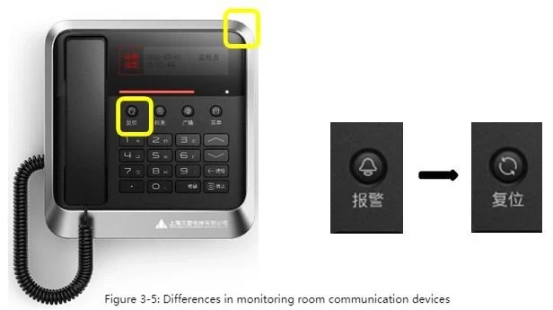
Compared with the monitoring room communication device with mobile communication module, there are the following differences:
▲ No mobile communication module and antenna;
▲ The "alarm" key is changed to the "reset" key;
▲ There is no "remote setting" and "alarm number setting" in the menu function, and "alarm filter setting" is added
2.3.4.2.2.1 “Reset” function
In the received call query menu, you can check the status of received calls. Press the "Reset" key to reset the alarm call information. After resetting, the "Alarm Already Sent Indicator Light" signal and "Alarm Already Registered Indicator Light" on the control box go out.
2.3.4.2.2.2 Alarm filter settings
Press the "∧" and "∨" keys on the keyboard, select the "Alarm Filter Settings" menu, press "Confirm", and you will be prompted to enter the password. After entering the correct password, press "Confirm" to enter the Alarm Filter Settings interface. The display screen will show the lower menu:
1. Filter valid ID list
2. Add valid devices
3. Delete valid devices
4. Set all as valid
5. Set all as invalid
6. Return to the previous level
a) Filter valid ID list
In the Alarm Filter Settings interface, press the "∧" and "∨" keys, select the "Filter valid ID list" menu, press "Confirm" to enter the interface. The filter valid ID and alias configuration are displayed. Press the "∧" and "∨" keys to turn pages. If the record is empty, it will prompt that there is no record.
b) Add valid devices
In the Alarm Filter Settings interface, press the "∧" and "∨" keys on the keyboard, select the "Add valid device" menu, and press "Confirm". The prompt "Please enter the newly added device ID" is displayed. Enter an existing ID number in the range of "003-999". After pressing "Confirm", it will prompt that the addition is successful.
c) Delete valid devices
In the alarm filter setting interface, press the keyboard "∧" and "∨" keys, select the "Delete valid device" menu, and press "Confirm". The prompt "Please enter the device ID to be deleted", enter an existing ID number in the range of "003-999". After pressing "Confirm", it will prompt that the deletion is successful.
d) Set all to valid
In the alarm filter setting interface, press the keyboard "∧" and "∨" keys, select the "Set all to valid" menu, and press "Confirm". Set the alarm filter of all IDs in the monitoring room communication device system to valid, and the configuration is successful after completion.
e) Set all to invalid
In the alarm filter setting interface, press the keyboard "∧" and "∨" keys, select the "Set all to invalid" menu, and press "Confirm".
Set the alarm filter of all IDs in the monitoring room communication device system to invalid. After completion, it will be displayed that the configuration is successful.
f) Return to the previous level
Select the "Return to the previous level" menu and press "Confirm" to jump to the previous level menu interface.
2.3.5 Configuration of fire elevators
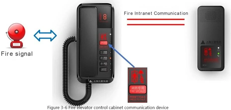
When the elevator is a fire elevator, the additional configuration is shown in Figure 3-6.
2.3.5.1 Added interfaces and components
On the control cabinet intercom device:
▲ Fire status input signal
▲ Fire intranet communication
▲ Fire dedicated button
Firefighter entrance floor intercom device
2.3.5.1 Basic operations and functions
When entering the fire state:
▲ The firefighter entrance floor intercom automatically establishes communication with the car intercom, and the fire intercom indicator flashes.
▲ Other buttons on the control cabinet intercom are invalid, and only the fire special button is valid.
▲ The control cabinet intercom changes to hands-free communication mode.
▲ The control cabinet intercom can only listen to the voice of the car intercom and the firefighter entrance floor intercom. Only by continuously pressing the fire special button can you have a multi-party conversation with the car intercom and the firefighter entrance floor intercom.
2.3.6 Control cabinet intercom box (machine roomless elevator)
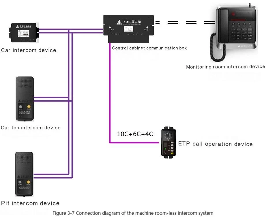
In case of machine room-less elevator, the control cabinet intercom device is replaced by the control cabinet intercom box and ETP intercom operating device. See Figure 3-7 for the connection diagram.
2.3.6.2 Basic operations and functions
Except for the following items, other operating methods are the same as the control cabinet communication device, see 3.3.
2.3.6.2.1 Call Mode
The talking part is an ETP talking operation device, hands-free mode.
2.3.6.2.2 Slave intercom device registration function
The installation registration method of the control cabinet call box is as follows:
▲ While the control cabinet call box is powered on, press and hold the 1 key of the ETP call operating device, and the display window displays 1, indicating that it has entered the installation registration mode. The factory default is that the car, car top, and pit call devices are all registered and installed.
▲ After entering the installation registration mode
▷ Press the "1" key of the ETP call operating device to set whether the car is registered and installed. Each time the button is pressed, the display window will display "1" or "0" in a cycle. 1 means registered installation, and 0 means unregistered installation.
▷ Press the "2" key of the ETP call operating device to set whether the car top is registered and installed. Each time the button is pressed, the display window will display "1" or "0" in a cycle. 1 means registered installation, and 0 means unregistered installation.
▷ Press the "3" key of the ETP call operating device to set whether the pit is registered and installed. Each time the button is pressed, the display window will display "1" or "0" in a cycle. 1 means registered installation, and 0 means unregistered installation.
▲ Press the "Monitoring Room" button on the ETP call operation device to view the setting results of the registered installation.
▲ After the setting is completed, the control cabinet call box is powered off and restarted to save the setting.
2.3.6.2.3 ID Setting
The ID of the control cabinet intercom box (machine roomless elevator) must be set when the external network communication is normal and the control cabinet intercom device is in standby. The setting method is as follows:
▲ Press and hold the "Fn" key of the ETP intercom operating device, and then:
▲ Set the thousands digit: long press the "1" key, the display window will display the "0~9" digits in a cycle. Release the "1" key when the display window displays the number you want to select, and the number is set as the thousands digit in the ID.
▲ Set the hundreds digit: long press the "2" key, the display window will display the "0~9" digits in a cycle. Release the "2" key when the display window displays the number you want to select, and the number is set as the hundreds digit in the ID.
▲ Set the tens digit: long press the "3" key, the display window will display the "0~9" digits in a cycle. Release the "3" key when the display window displays the number you want to select, and the number is set as the tens digit in the ID.
▲ After the three digits are set, long press the "M" key, and the display window will display the settings.
▲ After releasing the "Fn" key, the control cabinet intercom box will upload the ID number to the monitoring room intercom device. After the upload is successful, the display window will display "1". If the display window displays "0", it means that the ID already exists and the upload is unsuccessful, and the ID must be reset.
▲ Complete the setting after powering off and restarting.
Note: Pressing the "Fn" key can put the control cabinet intercom box in the on-hook state.
Note: Only after setting the phone ID according to the above operation and saving it in the monitoring room intercom device, the elevator room, car, car top, and pit intercom devices can communicate with the monitoring room intercom device.
2.3.6.2.4 Fire Elevator
There is no fire-related special key on the ETP call operating device.
When entering the fire state, the ETP call operating device, the firefighter entrance floor call device and the car call device automatically establish a three-party call.


