
Table of Contents
1. Device Function & Safety Specifications
1.1 Core Functions
-
Trigger Conditions:
-
Unlocked landing door AND open cAr door
-
Single component failure in drive system (excluding ropes/pulleys)
-
-
Protection Action:
-
Force stop within 0.5 seconds after triggering
-
1.2 Safety Levels
| Icon | Type | Content | Requirement |
|---|---|---|---|
| ⚠️ | Warning | Electric shock/mechanical hazards | Power off required |
| 🔧 | Note | Parameter errors | Certified personnel only |
| 💡 | Tip | Efficiency tips | Recommended priority |
2. Installation Configuration
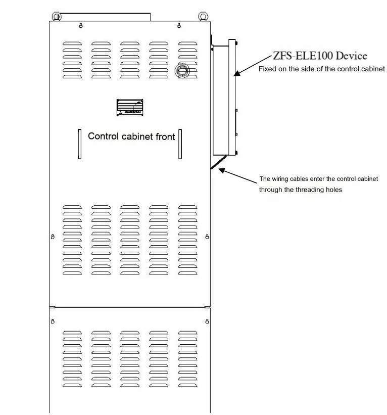
2.1 External Device (ZFS-ELE100)
2.1.1 Machine Room Installation
-
Positioning:
-
Fix housing to control cabinet with M8 bolts (right side preferred)
-
Torque: 12±1N·m (calibrated torque wrench)
-
-
Wiring:
-
Power lines (red/black) → PAD terminal L1/L2
-
Signal lines (yellow/blue) → P1 board X9A-3/X9A-4
-
Secure cables with nylon ties every 30cm (bend radius >5× cable diameter)
-
Acceptance Criteria:
-
Housing levelness ≤1mm/m
-
Ground resistance <0.1Ω
2.1.2 Machine-Room-Less Installation
Step-by-Step:
-
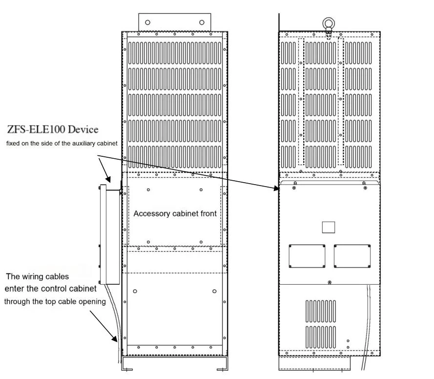
Auxiliary Cabinet Mounting:
-
Secure to right inner wall using M6 stainless bolts
-
Bolt spacing: 150mm horizontal, 200mm vertical
-
-
Top Entry Wiring:
-
Install rubber grommets in cable entry holes
-
Maintain ≥50mm separation between signal/power cables
-
2.2 Embedded Device (KCA-1009A)
-
Pre-Installed: Adjacent to P1 board in control cabinet (no field installation)
-
Verification:
-
Check P1 board LEDs post-power-on:
-
Green steady: Power OK
-
Red flashing: Signal not ready (check X9 connector)
-
-
3. Inspection & Maintenance
3.1 Periodic Inspection
| Item | Frequency | Tools | Acceptance Criteria |
|---|---|---|---|
| Brake Force Test | 6 months | Laser rangefinder | 5-test average ≤ Table 1 limits |
| Contact Impedance | 1 month | Multimeter (Fluke 87V) | NC contacts <0.5Ω |
3.2 Maintenance Protocols
Brake Force Deficiency Resolution:
-
Clean brake linings: Use 120-grit sandpaper on friction surfaces
-
Adjust spring pressure: Turn adjustment nut clockwise (1/4 turn per step)
-
Retest until compliant
⚠️ Warning:
-
Record spring compression length during disassembly (photo documentation)
-
Prohibit lubricants on friction surfaces
4. Stopping Distance Measurement
4.1 Synchronous Motor System (Machine Room)
4.1.1 Pre-Test Preparation
-
Tools:
-
Laser rangefinder (±1mm accuracy)
-
Insulated gloves (CAT III 1000V)
-
Jumper wire (0.5mm² Y/G)
-
-
Parameter Setup:
SET1=0 → SET0=8 → Press SW1 (enter Mode B)
MON1=0 → MON0=5 → Display current speed
4.1.2 Operational Steps
-
Car Positioning:
-
Empty car at top floor (leveling error <2mm)
-
Manually close hoistway and car doors
-
-
Mode Switching:
-
Disconnect EDSW connector (control cabinet X10 terminal)
-
Set emergency operation switch to "Emergency"
-
-
Downward Movement:
-
Hold "DOWN" button until DZ LED extinguishes → Release immediately
-
-
Measurement:
-
Measure vertical offset (X) between car/landing sills using laser rangefinder
-
Formula: Stopping distance S=150-X (mm)
-
-
Reset:
-
SET1=0 → SET0=8 → Press SW1 (exit Mode B)
-
Reconnect EDSW and reset emergency switch
-
4.1.3 Data Recording
| Test Cycle | Offset X (mm) | Stopping Distance S (mm) | Pass/Fail |
|---|---|---|---|
| 1 | +25 | 125 | ✔️ |
| 2 | +18 | 132 | ✔️ |
Pass Criteria: 5-test average ≤ Table 1 limits (e.g., ZBK-PMN ≤500mm)
4.2 Asynchronous Motor System (HOPE-IIG)
4.2.1 Test Tool Integration
-
Tool Connection:
-
Power off → Connect P295057C000G02 tool in series with PAD-X3 interface
-
Confirm tool LED shows steady red
-
-
Signal Trigger:
-
Disconnect RLD (Down) connector → Car moves 10mm → System logs "90b" fault
-
4.2.2 Distance Calculation & Reset
-
Measurement Rule:
-
Car sill below landing sill → X is negative (e.g., X=-20mm)
-
Formula: S=|X|+10=30mm
-
-
Reset Procedure:
-
Reconnect RLD → Power cycle → SET1=7 → SET0=E → Hold SW1 for 3s
-
5. Brake Fault Simulation & Reset
5.1 Brake OFF Fault (Failure to Release)
Step 1: Locate Terminals
-
BK1 Contacts: P1 board X5 terminal block
-
X5-1: BK1 NC input
-
X5-2: BK1 NC output
-
Step 2: Short-Circuit Operation
-
Connect X5-1/X5-2 with jumper wire → Power on → System logs "F1-BK1 OFF"
Step 3: Reset
-
Remove jumper → SET1=7 → SET0=E → Hold SW1 for 3s → Power cycle
5.2 Brake ON Fault Simulation (Failure to Engage)
Step 1: Disconnect Monitoring Circuit
-
Remove X5-3 connector → Power on → System logs "E2-BK1 ON"
Step 2: Reset
-
Reconnect X5-3 → Hard reset (power cycle)
6. Appendix: Key Diagrams & Tools
6.1 Brake Contact Locations
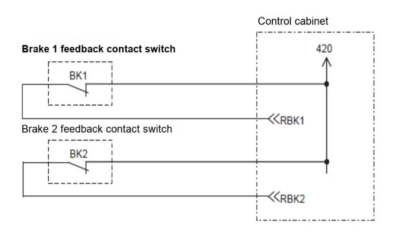
Diagram: X5 terminal block & shorting operation
6.2 Debugging Tool Connection
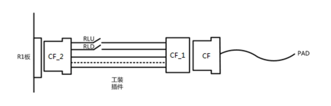
Diagram: Tool connection direction & LED status
6.3 Sill Gap Measurement
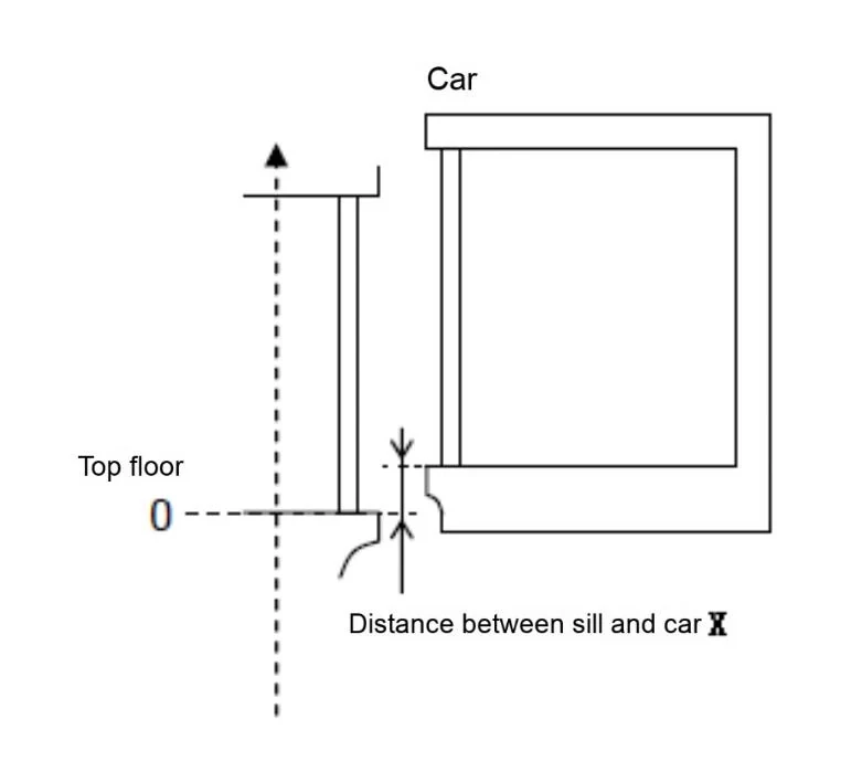
Diagram: Car & landing sill midpoint alignment
Disclaimer:
-
⚠️ All operations require certified personnel. Unauthorized modifications void warranties.


