
Table of Contents
-
-
Mechanical Requirements
-
Switch Activation Positions
-
-
-
Manual Mode Procedures
-
UOT/DOT Verification
-
-
-
Virtual UL/DL Function
-
Position Measurement
-
-
-
Error Codes
-
Reset Methods
-
1. Installation
1.1 Mechanical Requirements
-
Bracket Mounting:
-
No contact with switches, guide rails, or connectors
-
≥50mm cleArance for sliding rail clamps
-
Seal deep holes with covers
-
-
Buffer Configuration:
-
Ensure UOT/DOT activates before spring buffer contact
-
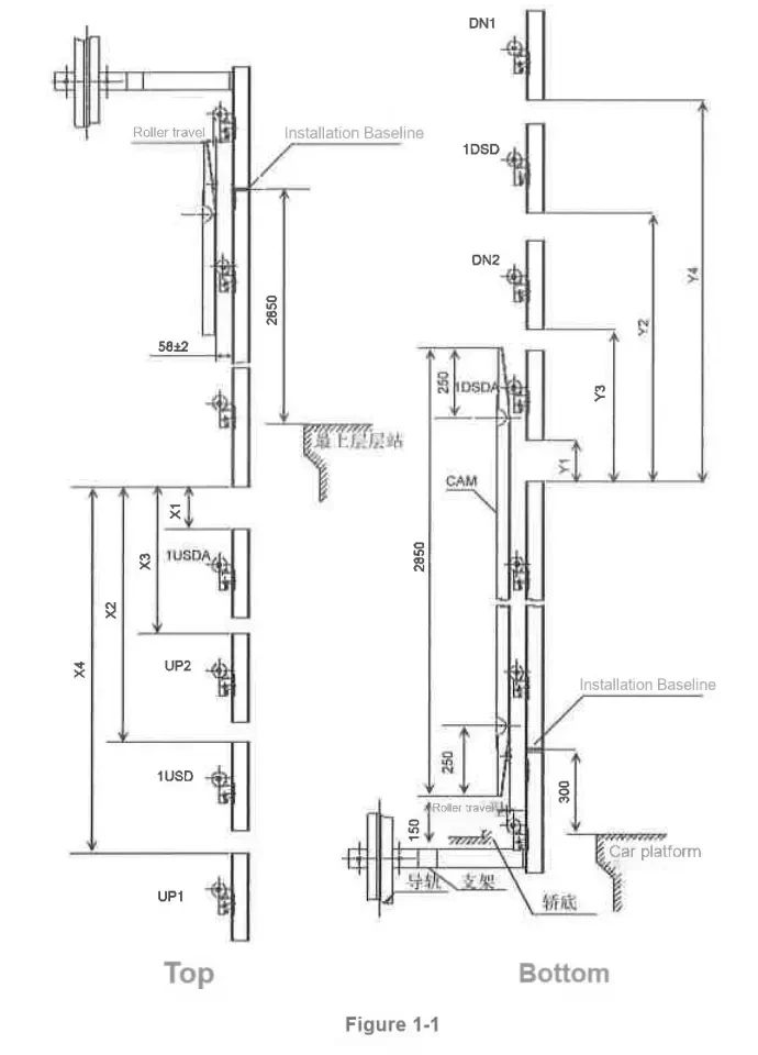
Diagram: Safety clearances for brackets and buffers
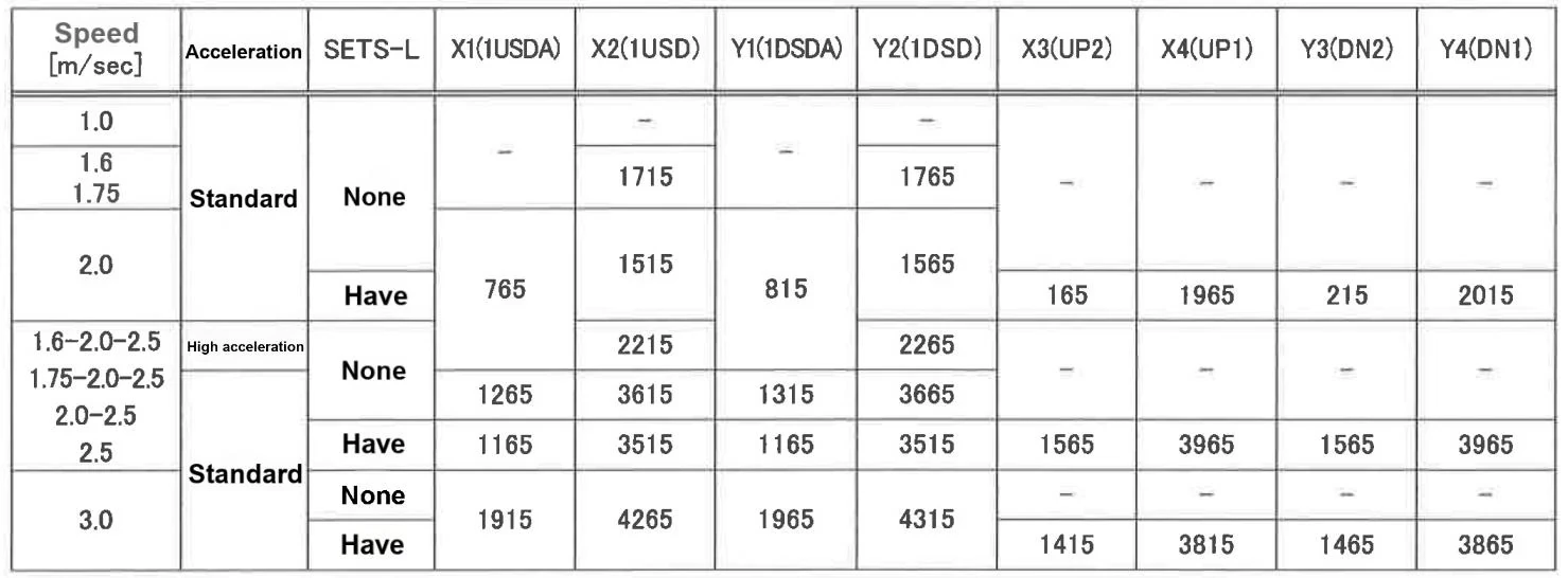
1.2 Switch Activation Positions
| Speed (m/s) | Activation Position [mm] (±15mm) | Sets Installed | Remarks |
|---|---|---|---|
| 1.0 | USR/DSR=1450 | 2 | Standard Configuration |
| 1.6 | USR/DSR=2400, IUSD/AIDSDA=3400 | 2 | UL/DL Disabled |
| 1.75 | USR/DSR=1900, IUSD=3550 | 2 | *3 Variable-speed |
| 2.0 | USR/DSR=4050 (3550*) | 3 | *2 High-acceleration |
| 2.5 | USR/DSR=4700, IUSD/IDSD=7050 | 3 | *3 Variable-speed |
| 3.0 | IUSD/IDSD=1915-4265 | 3 | Safety Loop Required |
Notes:
*2: Use values in brackets for high-acceleration models (e.g., 3550 for 2.0m/s)
*3: Applies only to variable-speed elevators
Installation Sets:
Speed≤1.75m/s: 2 sets (UOT/DOT)
Speed≥2.0m/s: 3 sets (UOT/DOT/USR/DSR)
1.3 Critical Notes
-
Speed vs. Sets:
-
For 1.6、1.75m/s: Install 2 sets (UOT/DOT)
-
For 2.0、2.5、3.0m/s: Install 3 sets (additional USR/DSR)
-
-
Special Configurations:
-
High-acceleration models (*2) must use bracketed values (e.g., 3550mm at 2.0m/s)
-
Variable-speed elevators (*3) require virtual UL/DL function (Chapter 3)
-
2. Debugging
2.1 Manual Mode Debugging
-
Low-Speed Positioning:
-
Move car to terminal floor at 20m/min (error <5mm)
-
Switch to 4m/min (
SET1/0=0/4, Mode A)
-
-
Trigger Verification:
-
View results via
MON1=3+MON0=A/Bafter activation
-
2.2 Manual Mode Parameters
| Step | Operation | Parameter Settings | Table Reference |
|---|---|---|---|
| 1 | Low-speed positioning (20m/min) | SET1/0=0/4 (Mode A) | Applies to all speeds |
| 2 | Terminal trigger (4m/min) | MON1=3+MON0=A/B | Select USR/DSR per speed |
2.3 UOT/DOT Verification
| Step | UOT Check (Upward) | DOT Check (Downward) |
|---|---|---|
| 1 | Disable UL switch | Disable DL switch |
| 2 | Ascend until #29 light off | Descend until #29 light off |
| 3 | Record position (no obstruction) | Record position (no obstruction) |
Warning: Do NOT short-circuit UL/DL during debugging.
3. Special Functions
3.1 Virtual UL/DL Function
-
Activation:
-
Auto-stop at virtual positions during manual operation
-
Buzzer sounds upon triggering
-
-
Deactivation:
-
Disabled during FMS activation
-
Restore via
SET1/0=7/E(Mode B)
-
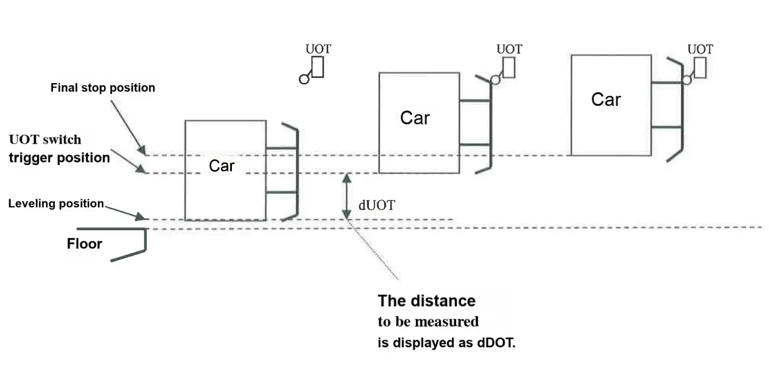
3.2 UOT/DOT Position Measurement
Procedure:
-
Position car at top/bottom floor (error <5mm)
-
Control panel settings:
-
SET1=0+SET0=0→ Press SW1V (Mode B) -
SET1=0+SET0=A/B→ Press SW1V
-
-
Move at 4m/min; stop upon trigger
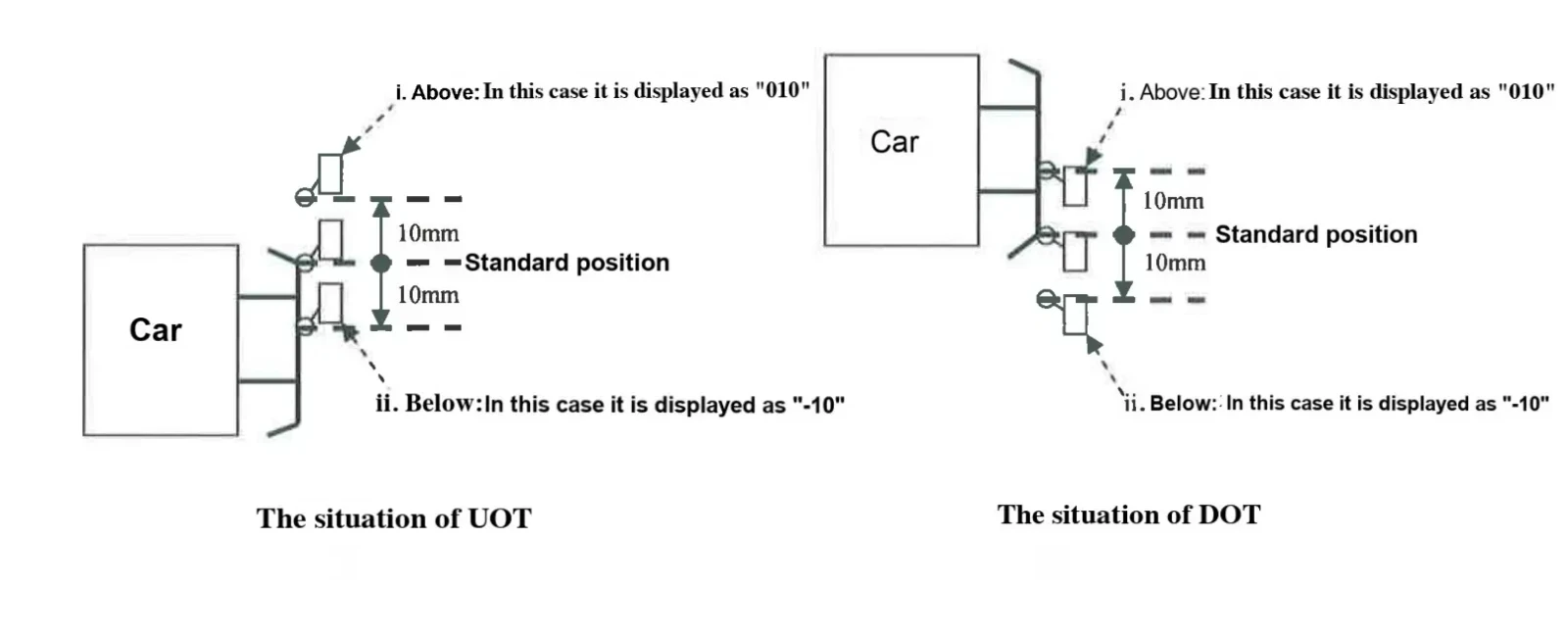
- Error codes:
010(+10mm),-10(-10mm)
4. Error Handling
4.1 Error Codes
| Code | Meaning |
|---|---|
010 | Switch triggered 10mm above standard |
-10 | Switch triggered 10mm below standard |
4.2 Reset Methods
-
Standard: Use ED switch
-
Emergency: Short-circuit R1 board 75-77 (if ED unavailable)
Disclaimer:
-
Data subject to field configuration. Unauthorized redistribution prohibited.


