
1 Overview
The PS (Power Supply) circuit provides critical power to elevator subsystems, categorized into conventional power systems and emergency power systems.
Key Power Designations
| Power Name | Voltage | Application |
|---|---|---|
| #79 | Typically AC 110V | Drives main contactors, safety circuits, door locks, and brake systems. |
| #420 | AC 24–48V | Supplies auxiliary signals (e.g., leveling switches, limit switches, relays). |
| C10-C00-C20 | AC 100V | Powers car equipment (e.g., car top station, operation panel). |
| H10-H20 | AC 100V | Supplies landing devices (converted to DC via power boxes for low-voltage use). |
| L10-L20 | AC 220V | Lighting circuits. |
| B200-B00 | Varies | Specialized equipment (e.g., regenerative braking systems). |
Notes:
-
Voltage levels may vary by elevator model (e.g., #79 in machine-room-less elevators matches #420 voltage).
-
Always refer to model-specific technical manuals for exact specifications.
Conventional Power Systems
-
Transformer-Based:
-
Input: 380V AC → Output: Multiple AC/DC voltages via secondary windings.
-
Includes rectifiers for DC outputs (e.g., 5V for control boards).
-
Supplementary transformers may be added for high-capacity landing devices or safety lighting.
-
-
DC-DC Converter-Based:
-
Input: 380V AC → DC 48V → Inverted to required DC voltages.
-
Key Difference:
-
Imported systems retain AC power for landing/car top stations.
-
Domestic systems fully convert to DC.
-
-
Emergency Power Systems
-
(M)ELD (Emergency Landing Device):
-
Activates during power outages to drive the elevator to the nearest floor.
-
Two types:
-
Delayed Activation: Requires confirmation of grid failure; isolates grid power until operation completes.
-
Instant Backup: Maintains DC bus voltage during outages.
-
-
Precharge/Discharge Circuits
-
Function: Safely charge/discharge DC link capacitors.
-
Components:
-
Precharge resistors (limit inrush current).
-
Discharge resistors (dissipate residual energy post-shutdown).
-
-
Fault Handling: See MC Circuit section for regenerative system issues.
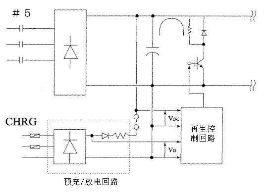
Precharge Circuit Schematic
2 General Troubleshooting Steps
2.1 Conventional Power System Faults
Common Issues:
-
Fuse/Circuit Breaker Tripping:
-
Steps:
-
Disconnect the faulty circuit.
-
Measure voltage at the power source.
-
Check insulation resistance with a megohmmeter (>5MΩ).
-
Reconnect loads one by one to identify the faulty component.
-
-
-
Abnormal Voltage:
-
Steps:
-
Isolate the power source and measure output.
-
For transformers: Adjust input taps if voltage deviates.
-
For DC-DC converters: Replace the unit if voltage regulation fails.
-
-
-
EMI/Noise Interference:
-
Mitigation:
-
Separate high/low voltage cables.
-
Use orthogonal routing for parallel lines.
-
Ground cable trays to reduce radiation.
-
-
2.2 Precharge/Discharge Circuit Faults
Symptoms:
-
Abnormal Charging Voltage:
-
Check precharge resistors for overheating or blown thermal fuses.
-
Measure voltage drop across components (e.g., resistors, cables).
-
-
Extended Charging Time:
-
Inspect capacitors, balancing resistors, and discharge paths (e.g., rectifier modules, busbars).
-
Diagnostic Steps:
-
Disconnect all DCP (DC Positive) connections.
-
Measure precharge circuit output.
-
Reconnect DCP circuits incrementally to locate abnormal discharge paths.
2.3 (M)ELD System Faults
Common Issues:
-
(M)ELD Fails to Start:
-
Verify #79 power signal during grid failure.
-
Check battery voltage and connections.
-
Inspect all control switches (esp. in machine-room-less setups).
-
-
Abnormal (M)ELD Voltage:
-
Test battery health and charging circuits.
-
For systems with boost transformers: Verify input/output voltage taps.
-
-
Unexpected Shutdown:
-
Check safety relays (e.g., #89) and door zone signals.
-
3 Common Faults & Solutions
3.1 Voltage Abnormalities (C10/C20, H10/H20, S79/S420)
| Cause | Solution |
|---|---|
| Input Voltage Issue | Adjust transformer taps or rectify grid power (voltage within ±7% of rated). |
| Transformer Fault | Replace if input/output voltage mismatch persists. |
| DC-DC Failure | Test input/output; replace the converter if defective. |
| Cable Fault | Check for grounding/short circuits; replace damaged cables. |
3.2 Control Board Failure to Power On
| Cause | Solution |
|---|---|
| 5V Supply Issue | Verify 5V output; repair/replace PSU. |
| Board Defect | Replace the faulty control board. |
3.3 Transformer Damage
| Cause | Solution |
|---|---|
| Output Short Circuit | Locate and repair grounded lines. |
| Unbalanced Grid Power | Ensure 3-phase balance (voltage fluctuation <7%). |
3.4 (M)ELD Malfunction
| Cause | Solution |
|---|---|
| Start Conditions Not Met | Inspect control switches and wiring (esp. in machine-room-less systems). |
| Low Battery Voltage | Replace batteries; check charging circuits. |
3.5 Precharge/Discharge Circuit Issues
| Cause | Solution |
|---|---|
| Input Power Fault | Rectify grid voltage or replace the power module. |
| Component Failure | Test and replace faulty parts (resistors, capacitors, busbars). |
Document Notes:
This guide aligns with Mitsubishi elevator standards. Always follow safety protocols and consult technical manuals for model-specific details.
© Elevator Maintenance Technical Documentation


