
1. SET Switch Functional Overview
1.1 SET1/SET0 Functional Matrix
| SET1 | SET0 Range | Function | Description |
|---|---|---|---|
| 0 | 0–F | Debug Mode Configuration | Set pArameters, then press SW1▽ to activate. Debug mode displays on 7SEG. |
| 1 | 0–F | PTSH Adjustment | Leveling position correction parameter. |
| 2 | 0–F | DNSH Adjustment | Door operation timing parameter. |
| 3 | 0–F | WGHG Adjustment | Startup gain tuning for load compensation. |
| 4 | 0–F | WGHO Adjustment | Overload compensation parameter. |
| 5 | 0–F | TSSH Adjustment | Terminal slowdown delay constant. |
| 6 | 0–F | WGCPN Adjustment | Load-dependent leveling compensation. |
| 8 | 0–F | Advanced Debug Mode | Secondary debug functions (7SEG display). |
| E | 0–F | Signal Monitoring | Real-time signal display on 7SEG. |
| Other | ―― | *Reserved/Undefined* | ―― |
1.2: SET1/SET0 Configuration Procedure
-
Select Function:
-
Align SET1/SET0 with target parameter from the functional matrix.
-
-
Activate Mode:
-
Press SW1▽ to confirm.
-
7SEG displays current Flash Memory data.
-
-
Modify Value:
-
Press SW1▽ again to overwrite Flash Memory with the new SET0 value.
-
-
Validation:
-
Updated data reflects on 7SEG.
-
1.3 Key Applications
-
Debug Mode (SET1=0/8):
-
Use for system diagnostics or firmware updates.
-
-
PTSH/DNSH (SET1=1/2):
-
Fine-tune leveling accuracy and door operations.
-
-
WGCPN (SET1=6):
-
Compensate ±7mm leveling offsets (1 SET0 step = 1mm).
-
2. Debug Functions for SET1=0
2.1 SET1=0 Functional Matrix
| SET0 | Function | LED Display | Key Actions |
|---|---|---|---|
| 0 | Default Mode | Restores MON1/0 settings | Disables debug functions. |
| 2 | Empty Load (NL) Data Write | Installation Phase | Writes empty car weight to Flash Memory. |
| 3 | Half Load (BL) Data Write | Installation Phase | Writes 50% rated load data to Flash Memory. |
| 4 | Overload (OL) Data Write | Installation Phase | Writes 110% rated load data to Flash Memory. |
| 5 | Empty Load (NL) Maintenance | Maintenance Phase | Updates empty load data & auto-adjusts BL. |
| 6 | HAND Priority Mode | H + Floor Number (e.g., H5) | Forces manual control priority. |
| B | Brake Slip Measurement | Real-time slip value (0–999) | Validates brake performance. |
| C | Overload Buzzer Test | Continuous buzzer when SW1 held | Auditory alarm verification. |
| D | Magnetic Pole Learning | Flashing → Steady 7SEG | Motor pole position initialization. |
| F | TSD Operation Test | TSD switch codes (e.g., [1][u]) | Terminal slowdown system validation. |
2.2 Load Data Programming Protocol
Flash Memory Write Procedure
-
SET1=0 + Target SET0:
-
NL (SET0=2): Empty load calibration.
-
BL (SET0=3): 50% load calibration.
-
OL (SET0=4): 110% overload calibration.
-
-
Steps:
-
Set SET1=0 + desired SET0 (e.g.,
2for NL). -
Press SW1▽ → 7SEG displays current Hex value.
-
Press SW1▽ again to overwrite Flash Memory.
-
-
Maintenance Mode (SET0=5):
-
Automatically adjusts BL data after NL update.
-
2.3 Special Function Activation
| Function | Steps | 7SEG Feedback |
|---|---|---|
| Brake Slip Test | SET0=B → SW1▽ → Manual run | Slip value (e.g., 250) |
| Buzzer Test | SET0=C → Hold SW1 >3 sec | Continuous buzzer tone |
| TSD Test | SET0=F → Terminal runs | TSD switch codes (e.g., [u][S][r]) |
3. Display Functions for SET1=E
3.1 SET1=E Functional Matrix
| SET0 | Display Content | Format | Key Notes |
|---|---|---|---|
| 0 | Floor Number | [Status] + [Floor] | Standard operation mode. |
| 2 | Empty Load (NL) Data (HEX) | Hexadecimal value | Press SW1△ for decimal conversion. |
| 3 | Half Load (BL) Data (HEX) | Hexadecimal value | Press SW1△ for decimal conversion. |
| 4 | Overload (OL) Data (HEX) | Hexadecimal value | Press SW1△ for decimal conversion. |
| 5 | Speed Feedback (Peak) | [Speed] (1m/min per digit) | Captures maximum recorded speed. |
| 6 | Speed Feedback (Real-Time) | [Speed] (1m/min per digit) | Live motor RPM monitoring. |
| 7 | Model Speed Reference (Real-Time) | [Speed] (1m/min per digit) | Compares actual vs. theoretical speed. |
| 8 | Current Load Data (HEX) | Hexadecimal value | Real-time load measurement. |
| 9 | Car Position (Leveling Detection) | [Floor].[0–6/E] | E.g., 4 = fully leveled at floor 4. |
| D | Mid-Shaft Position Deviation | ±[Value] (256mm per digit) | Negative = below mid-shaft; Positive = above. |
| E | Bottom Floor Leveling Deviation | [Value] (1m per digit) | Distance from bottom floor leveling zone. |
| F | Current Load Percentage | [Value]% (1% per digit) | Real-time load capacity (0–110%). |
| *A/B/C* | *Reserved/Undefined* | ―― | ―― |
3.2 Key Operational Notes
-
HEX ↔ Decimal Conversion:
-
For SET0=2/3/4/8, press SW1△ to toggle between HEX and decimal formats.
-
-
Position Diagnostics:
-
SET0=9:
Eindicates *out-of-leveling-zone* status. -
SET0=D:
-99= 25.3m below mid-shaft;+99= 25.3m above.
-
-
Load Monitoring:
-
SET0=F: Displays live load percentage (e.g.,
75= 75% capacity).
-
3.3 Example Use Cases
-
Leveling Calibration Check:
-
Set SET0=9 → Verify car is fully leveled (e.g.,
4= floor 4 aligned).
-
-
Overload Verification:
-
Set SET0=F → Confirm load ≤110% during test runs.
-
-
Speed Discrepancy Analysis:
-
Compare SET0=6 (Real-Time) vs. SET0=7 (Model) to identify drive issues.
-
4. Fault Code Diagnostics
4.1 Fault Code Interpretation
Set rotary switches to MON1=0, MON0=0 to display active faults on 7SEG1/2. Blinking indicates unresolved issues.
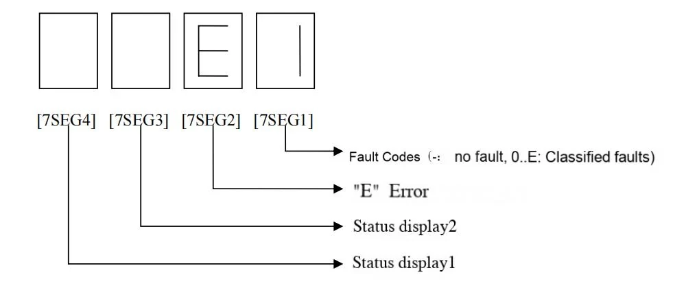
| 7SEG1 | 7SEG2 | Fault Category | Critical Components |
|---|---|---|---|
| 0 | — | Inverter Unit Fault | IGBT modules, drive circuits |
| 1 | — | Rectifier Unit Components | KCN-100X surge absorber, capacitors |
| 2 | — | Rectifier Board Issues | KCR-101X (E1) / KCR-102X (F1) PCBs |
| 3 | — | Power Supply System | Control voltage circuits (DC48V/125V) |
| 4 | — | Control Panel Relays | NF-CP, NF-SP, SCB breakers |
| 5 | — | Safety Circuit Relays | 29/60 relays, door lock circuits |
| 6 | — | Safety Loop Fault | GOV, BTP, UL/DL switches |
| 7 | — | Door System Error | Door operator, CSC/DSR signals |
| 8 | — | Shaft Switch Malfunction | TSD, USR/DSR, leveling sensors |
| 9 | — | Brake/Traction System | Brake coils, motor encoder |
| A | — | Speed Control & Selector | P1 board speed feedback, FMS data |
| B | — | Load Weighing System | TSD box, LIR-220 PCB |
| C | — | P1 Board Software Fault | Firmware corruption, memory errors |
| D | — | System Configuration Error | Parameter mismatches (e.g., TSSH) |
| E | — | Communication Failure | CAN bus, R1 board connectors |
| F | — | Reserved | ―― |
4.2 Operational Notes
-
Blinking Display:
-
Active faults cause 7SEG1/2 to blink until resolved.
-
-
Multi-Code Prioritization:
-
Simultaneous faults display highest-priority code (priority: 0 > 1 > ... > E).
-
-
Post-Repair Reset:
-
Clear codes by cycling power after fault resolution.
-


