
1. Installation & Adjustment of Critical Components
-
Door System Configuration:
-
Install and adjust landing and cAr door operators (including car-top station settings).
-
-
Leveling Sensor Setup:
-
Position and calibrate magnetic plate for precise floor alignment.
-
-
Terminal Safety Switches:
-
Install and adjust deceleration, limit, and final limit switches at shaft terminals.
-
-
Landing Station Devices:
-
Mount hall call buttons/displays and configure related potentiometers.
-
2. Pre-Commissioning Preparations
2.1 LED Status Verification
-
Confirm normal illumination of all board LEDs.
2.2 FMS Layer Data Initialization
Required before automatic operation to prevent "selector deviation" faults:
-
Manual Mode Setup:
-
Move the car to the bottom floor leveling zone via manual control.
-
Hold the FMS toggle switch downward for 2 seconds to activate layer data writing.
-
-
Continuous Upward Run:
-
Manually drive the car upward to the top floor until UL switch activates.
-
Critical: Do NOT stop mid-travel.
-
Success: Floor number display stops blinking at the top floor.
-
-
Failure Recovery:
-
If interrupted, restart from Step 1.
-
2.3 High-Speed Operation Sequence
-
Independent Mode (Optional):
-
Set the car operation panel’s "Independent" switch to ON if equipped.
-
-
Automatic Mode Activation:
-
Set ALL maintenance panel switches (car-top, car, landing) to AUTO.
-
Confirm LED 60 illuminates (extinguishes if any switch remains in MANUAL).
-
-
Call Button Test:
-
Press hall/car call buttons to verify indicator lights activate.
-
3. High-Speed Calibration Procedures
3.1 Balance Factor Adjustment
-
Load Setup:
-
Place 50% of the rated load in the car, centralized at the midpoint.
-
Position the car at the bottom floor.
-
-
Upward Run Measurement:
-
Run the elevator to the top floor in AUTO mode at rated speed.
-
Record the motor current when the car reaches the mid-shaft position.
-
-
Downward Run Measurement:
-
Repeat the test in the downward direction at rated speed.
-
Record the motor current at mid-shaft.
-
-
Counterweight Optimization:
-
Adjust counterweight blocks until current difference between upward/downward runs is ≤±1A.
-
3.2 Brake System Calibration
-
Plunger Stroke Adjustment:
-
Set brake plunger stroke to 0.6±0.1mm.
-
-
Brake Contact Gap Test:
-
No activation when inserting a 0.5mm feeler gauge.
-
Must activate with a 1.0mm feeler gauge.
-
-
Brake Slip Distance Verification:
-
Load the car with 110% rated load.
-
Configure P1 board settings:
-
Set R/M-MNT-FWR toggle to MNT.
-
Adjust potentiometers: SET1=0, SET0=B.
-
Press SW1▽ to confirm.
-
-
-
Manual Downward Run Test:
-
Press SW1▽ again.
-
Manually drive the car downward via machine room controls.
-
Monitor 7SEG display for real-time speed.
-
Emergency stop when speed reaches 20 m/min.
-
-
Slip Distance Validation:
-
Confirm 7SEG displays a brake slip value ≤300 (unitless metric).
-
3.3 Load Weighing System Calibration & Data Initialization
3.3.1 Differential Transformer Calibration
-
Empty Car Preparation:
-
Ensure no load in the car.
-
Technician 1 adjusts the differential transformer at the car bottom.
-
Technician 2 measures voltage at the car-top TSD box.
-
Safety Note: Stand on crossbeams/door operator frames – DO NOT stand directly on the car roof.
-
-
Voltage Adjustments:
-
TM1 (V1/V3 ↔ TM2 0V): DC2.2V ±0.2V
-
LIR-220 R02 Potentiometer (VB ↔ 0V): DC0.3V ±0.1V
-
VF ↔ 0V: DC-2.0V ±0.2V
-
3.3.2 Flash-Memory Data Initialization
Empty Load Data (0%)
-
Set P1 board: SET1=0, SET0=2 → Press SW1▽.
-
7SEG displays current load data.
-
-
Hold SW1▽ >1 sec until display stops blinking → Data saved.
-
Reset: SET1=0, SET0=6 → Press SW1▽.
Half-Load Data (50%)
-
Place 50% rated load near mid-shaft.
-
Set P1: SET1=0, SET0=3 → Press SW1▽.
-
If 7SEG shows "A300" or "AE00":
-
Adjust TSD R01 to VB ↔ 0V = DC+1.8V ±0.1V.
-
-
-
Hold SW1▽ >1 sec → Save data.
-
Reset: SET1=0, SET0=6 → Press SW1▽.
Overload Data (110%)
-
Place 110% load and adjust car-bottom stopper gap to 2mm.
-
Set P1: SET1=0, SET0=4 → Press SW1▽.
-
Hold SW1▽ >1 sec → Save data.
-
Reset: SET1=0, SET0=6 → Record OLWT on control panel nameplate.
3.3.3 Overload & Compensation Adjustments
Overload Action (29W)
-
Set P1: SET1=4 → Press SW1▽.
-
Adjust SET0 until 7SEG shows "oL" → Confirm doors remain open with alarm.
Compensation Deviation Correction
-
Place 50% load at bottom floor.
-
Set P1: SET1=8, SET0=3 → Press SW1▽ (auto-speed: 60m/min).
-
Press SW1▽ → SW2△ for upward run → SW2▽ for downward run.
-
Post-test:
-
Read compensation data via MON1=A, MON0=8/9 → Record CUWT.
-
Adjust HWLG (MON1=9, MON0=6) if startup jerks persist.
-
3.3.4 Startup Gain & Brake Slip Optimization
Startup Gain Fine-Tuning
-
For empty-car startup jerks:
-
Set car to mid-shaft in IND mode (SPA/IND switch).
-
Set P1: MON1=9, MON0=C → HTOP=0 (7SEG1).
-
Adjust WGHG (SET1=3 + SET0) until car remains stationary after brake release.
-
Reset HTOP=5.
-
Brake Slip Correction
-
Upward Slip (Fig 2-6):
-
Set SET1=3 → Increase SET0 (F direction) → Confirm with SW1.
-
-
Downward Slip (Fig 2-7):
-
Set SET1=3 → Decrease SET0 (1 direction) → Confirm with SW1.
-
4. TSD Switch Position Verification & High-Speed Testing
4.1 TSD Action Position Check
Temporary Parameter Setup
| Parameter | Rotary Potentiator | Value |
|---|---|---|
| TSSH | SET1=8, SET0=5 | 8 |
| DELY/TROD | MON1=9, MON0=E | DELY=8, TROD=4 |
-
Safety Precheck:
-
Confirm no "selector deviation" fault (blinking floor display) during empty-car terminal runs.
-
-
TSD Check Mode Activation:
-
Set P1: SET1=8, SET0=1 → Press SW1▽ (speed auto-sets to 60m/min).
-
-
Full-Shaft Test:
-
Press SW1▽ → SW2△ for upward run.
-
At top floor, press SW2▽ for downward run.
-
7SEG displays TSD switch deviations sequentially (see table below):
-
| TSD Switch | 7SEG Display | TSD Switch | 7SEG Display |
|---|---|---|---|
| 1U | [1][u][ ][-] | 1D | [1][d][ ][-] |
| 2U | [2][u][ ][-] | 2D | [2][d][ ][-] |
| ... | ... | ... | ... |
| USR | [u][S][r][-] | DSR | [d][S][r][-] |
-
Reset: Restore P1 parameters to defaults.
4.2 High-Speed Auto-Run Validation
-
Manual Mid-Shaft Positioning:
-
Drive the car to a mid-floor leveling zone via manual control.
-
-
Auto-Mode Configuration:
-
Set SPA/IND (P1) to center position.
-
Set AUTO/HAND (R1) to AUTO.
-
Ensure all car-top/car switches are in AUTO.
-
-
Multi-Floor Test:
-
Register adjacent floor calls for short auto-runs.
-
Verify smooth deceleration and leveling at each stop.
-
-
Full-Shaft Auto-Run:
-
Test multi-floor and terminal-to-terminal runs for consistent performance.
-
4.3 Magnetic Pole Position Learning
-
Empty Car Setup:
-
Position the car at the bottom floor.
-
-
Learning Mode Activation:
-
Set P1: SET1=0, SET0=d → Press SW1▽ (speed: 60m/min).
-
-
Data Initialization:
-
Press SW2△ → Car auto-runs to top floor.
-
Success: 7SEG stops blinking.
-
-
Reset: Restore SET1/SET0 to defaults.
4.4 Inertia Identification Run
-
Temporary Parameter Setup:
-
Apply parameters from TSD Check Step 1.
-
-
Test Mode Activation:
-
Position empty car at bottom floor.
-
Set P1: SET1=8, SET0=2 → Press SW1▽ (speed: 60m/min).
-
-
Terminal-to-Terminal Runs:
-
Press SW1▽ → SW2△/▽ → Car auto-runs between terminals.
-
Validate 7SEG3 displays "0–9" without blinking after two round trips.
-
-
Failure Recovery:
-
If 7SEG3 blinks, repeat TSD Check before retesting.
-
-
Reset: Restore all parameters.
5. DC-CT Gain Calibration & Leveling Precision Optimization
5.1 DC-CT Gain Identification
*Resolve motor current imbalance causing empty-car jerks (requires properly adjusted brakes):*
-
Preparation:
-
Set R/M-MNT-FWR to MNT.
-
Manually position the car mid-shaft at low speed.
-
-
Compensation Mode Activation:
-
Set P1: SET1=8, SET0=4 → Press SW1▽ twice.
-
-
Manual Upward Run (Simulated):
-
Hold manual UP switch for ≥50 seconds (brakes remain engaged; car stationary).
-
Success: 7SEG displays cumulative compensation count; data saved to memory.
-
-
Precision Optimization:
-
Repeat Step 3 3+ times for accuracy.
-
-
Reset: Restore SET1/SET0 to defaults.
5.2 Leveling Error Adjustment
5.2.1 PTSH Parameter Tuning
-
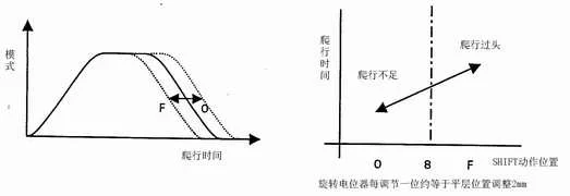
Symptom: Over-leveling or failure to reach leveling position.
-
Procedure:
-
Set P1: SET1=1 → Press SW1▽.
-
Adjust SET0 to modify PTSH → Press SW1▽ to confirm.
-
5.2.2 Magnetic Plate Repositioning
-
Recalibrate leveling sensor plate installation for alignment accuracy.
Load Compensation (WGCPN)
| SET0 | WGCPN Value | Leveling Adjustment |
|---|---|---|
| F | +7.0 mm | |
| E | +6.0 mm | |
| ... | ... | 1 step = 1mm |
| 4 | -4.0 mm |
-
Default Setup: SET1=6, SET0=8 (factory default = 0.0mm).
-
Adjust SET0 → Press SW1▽ to apply.
5.2.3 Brake Timing & Re-Leveling (LTB/RLPT)
-
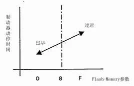
LTB (Brake Engagement Timing):
-
Too early: Increase LTB (F direction).
-
Too late: Decrease LTB (0 direction).
-
Tool Required: Service computer for E2PROM modification.
-
-
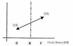
RLPT (Re-Leveling Precision):
-
Critical: Adjust only with micro-recorder/accelerometer for ride comfort compliance.
-
6 TSD Mode Calibration & Load Performance Validation
6.1 TSD Mode Delay Constant (TSSH) Setup
-
Initial Configuration:
-
Position empty car at bottom floor.
-
Set TSSH = DELY (retrieve DELY via MON1=9, MON0=E → check 7SEG2).
-
-
TSSH Adjustment:
-
Set P1: SET1=5 → Press SW1▽ → Adjust SET0 → Confirm with SW1▽.
-
-
Terminal Run Test:
-
Press SW2△/▽ → Run car between terminals at rated speed.
-
Increment TSSH until 7SEG1 blinks during deceleration → Stop (max TSSH reached).
-
6.2 TSD Operation Check
-
Mid-Shaft Setup:
-
Position empty car at mid-floor door zone.
-
Set TSSH = (Current Value – 2).
-
-
Test Mode Activation:
-
Set P1: SET1=0, SET0=F → Press SW1▽ twice.
-
-
Terminal Run Validation:
-
Press SW2△/▽ → Car runs terminal-to-terminal at rated speed.
-
Post-test:
-
Confirm car stops within door zone at bottom floor.
-
Validate 7SEG3 displays 3–5.
-
-
-
Over-Travel Correction:
-
If car overshoots terminal, increase TSSH by 1.
-
-
Reset: Restore P1 to SET1=0, SET0=6.
6.3 Load Performance Testing
Validate elevator operation across 0%–110% load:
| Checklist | Acceptance Criteria |
|---|---|
| Leveling Accuracy | ±5mm deviation |
| Ride Quality | Smooth acceleration/deceleration |
| Noise & Vibration | Meets ISO 18738 standards |
| Full-Load Upward Current | ≤ Motor nameplate rating |


