
1. Essential Safety Precautions
1.1 Power Safety Requirements
-
Capacitor DischArge Verification
-
After cutting the main elevator power, the DCV LED on the surge absorber board (KCN-100X) will extinguish within ~10 seconds.
-
Critical Action: Before servicing drive circuits, use a voltmeter to confirm the voltage across the main capacitors is near zero.
-
-
Group Control Panel Hazard
-
If a group control system is installed, the shared terminals (red-marked terminals/connectors) remain live even when a single elevator's control panel is powered off.
-
1.2 Control Panel Operational Guidelines
-
ESD Protection for Semiconductors
-
Avoid direct contact with base-triggered semiconductor components on E1 (KCR-101X) or F1 (KCR-102X) boards. Static discharge may damage IGBT modules.
-
-
IGBT Module Replacement Protocol
-
If an IGBT module fails, replace all modules within the corresponding rectifier/Inverter unit to ensure system integrity.
-
-
Foreign Object Prevention
-
Prohibit placing loose metal parts (e.g., screws) on the control panel top to avoid short-circuit risks.
-
-
Power-On Restrictions
-
Never energize the drive unit if any connectors are unplugged during commissioning or maintenance.
-
-
Workspace Optimization
-
In confined machine rooms, secure side/rear control panel covers before final installation. All servicing must occur from the front.
-
-
Parameter Modification Procedure
-
Set the R/M-MNT-FWR toggle switch to MNT position before altering elevator program parameters.
-
2. Power Supply Verification
2.1 Control Voltage Inspection
Verify input/output voltages across designated measurement points:
| Circuit Name | Protection Switch | Measurement Point | Standard Voltage | Tolerance |
|---|---|---|---|---|
| 79 | CR2 | Primary side ↔ Terminal 107 | DC125V | ±5% |
| 420 | CR1 | Primary side ↔ Terminal 107 | DC48V | ±5% |
| 210 | CR3 | Primary side ↔ Terminal 107 | DC24V | ±5% |
| B48V | BP | Primary side ↔ Terminal 107 | DC48V | ±5% |
| D420 (with MELD) | CLD | Primary side ↔ Terminal 107 | DC48V | ±5% |
| D79 (with MELD) | CLG | Primary side ↔ Terminal 107 | DC125V | ±5% |
| 420CA (2C2BC) | CLM | Primary side ↔ Terminal 107 | DC48V | ±5% |
P1 Board Power Supply Verification:
-
-12V to GND: DC-12V (±5%)
-
+12V to GND: DC+12V (±5%)
-
+5V to GND: DC+5V (±5%)
2.2 Car & Landing Power Supply Check
Validate AC voltage for cabin and landing systems:
| Power Circuit | Protection Switch | Measurement Point | Standard Voltage | Tolerance |
|---|---|---|---|---|
| Car Top Power (CST) | CST | Primary side ↔ Terminal BL-2C | AC200V | AC200–220V |
| Landing Power (HST) | HST | Primary side ↔ Terminal BL-2C | AC200V | AC200–220V |
| Auxiliary Landing Power | HSTA | Primary side ↔ Terminal BL-2C | AC200V | AC200–220V |
2.3 Connector & Circuit Breaker Inspection
-
Pre-Energization Steps:
-
Turn OFF NF-CP, NF-SP, and SCB switches.
-
Ensure all connectors on P1 and R1 boards are securely plugged in.
-
-
Sequential Power-On Protocol:
-
After activating NF-CP/NF-SP/SCB, power ON safety breakers and circuit protection switches one at a time.
-
For selective power circuits, confirm voltage compliance before closing switches:
Power Circuit Protection Switch Measurement Point Standard Voltage Tolerance DC48V ZCA Primary side ↔ Terminal 107 DC48V ±3V DC24V ZCB Primary side ↔ Terminal 107 DC24V ±2V -
-
Backup Power Warning:
-
DO NOT touch the secondary side of the BTP circuit protector – backup power remains active.
-
3. Motor Encoder Inspection
3.1 Encoder Testing Procedure
-
Power Isolation:
-
Turn OFF the NF-CP power switch.
-
-
Encoder Disconnection:
-
Remove the encoder connector on the traction machine side.
-
Loosen the encoder mounting screws.
-
-
PD4 Connector Verification:
-
Confirm secure connection of PD4 plug on the P1 board.
-
-
Voltage Check:
-
Turn ON NF-CP.
-
Measure voltage at the encoder connector:
-
Pins 1 (+) ↔ 2 (–): +12V ±0.6V (critical tolerance).
-
-
-
Reconnection Protocol:
-
Turn OFF NF-CP.
-
Reattach the encoder connector.
-
-
Parameter Configuration:
-
Turn ON NF-CP.
-
Set P1 board rotary potentiometers:
-
MON1 = 8, MON0 = 3.
-
-
-
Direction Simulation Test:
-
Rotate the encoder to simulate elevator UP direction.
-
Confirm 7SEG2 display shows "u" (refer to Figure 4).
-
If "d" appears: Swap encoder wiring pairs:
-
ENAP ↔ ENBP and ENAN ↔ ENBN.
-
-
-
Finalization:
-
Securely tighten encoder mounting screws.
-
4 LED Status Diagnostics
Refer to Figure 1 for board layouts.
| Board | LED Indicators | Normal State |
|---|---|---|
| KCD-100X | CWDT, 29, MWDT, PP, CFO | Illuminated |
| KCD-105X | WDT | Illuminated |
Critical Checks:
-
Rectifier Unit Validation:
-
After power-up, CFO on 7SEG must illuminate.
-
If CFO is off: Inspect power circuit wiring and phase sequence.
-
-
WDT Status Verification:
-
Confirm illumination of:
-
CWDT and MWDT (KCD-100X)
-
WDT (KCD-105X)
-
-
If WDT is off:
-
Check +5V supply and connector integrity.
-
-
-
Capacitor Charge Circuit Test:
-
DCV LED on capacitor board (KCN-1000/KCN-1010) must:
-
Illuminate when powered ON.
-
Extinguish ~10 seconds after power-off.
-
-
Abnormal DCV behavior: Diagnose:
-
Inverter unit
-
Charge/discharge circuits
-
Capacitor terminal voltage
-
-
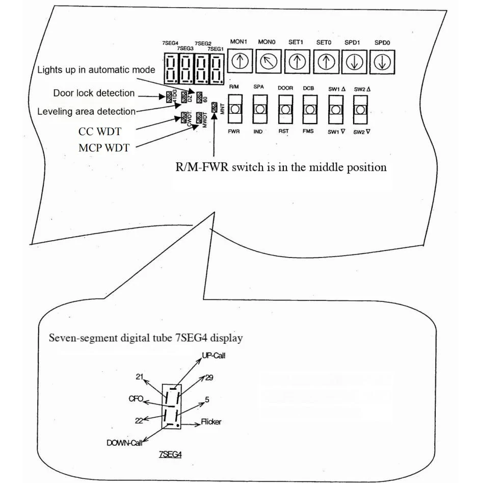
Figure 1 LED status on the P1 board


