
Hoistway Signal Circuit (HW)
1 Overview
The Hoistway Signal Circuit (HW) consists of leveling switches and terminal switches that provide critical position and safety information to the elevator control system.
1.1 Leveling Switches (PAD Sensors)
-
Function: Detect cAr position for floor leveling, door operation zones, and re-leveling areas.
-
Common Signal Combinations:
-
DZD/DZU: Main door zone detection (car within ±50mm of floor level).
-
RLD/RLU: Re-leveling zone (narrower than DZD/DZU).
-
FDZ/RDZ: Front/rear door zone signals (for dual-door systems).
-
-
Key Rule:
-
-
If either RLD/RLU is active, DZD/DZU must also be active. Violation triggers door zone safety protection (see SF Circuit).
-
-
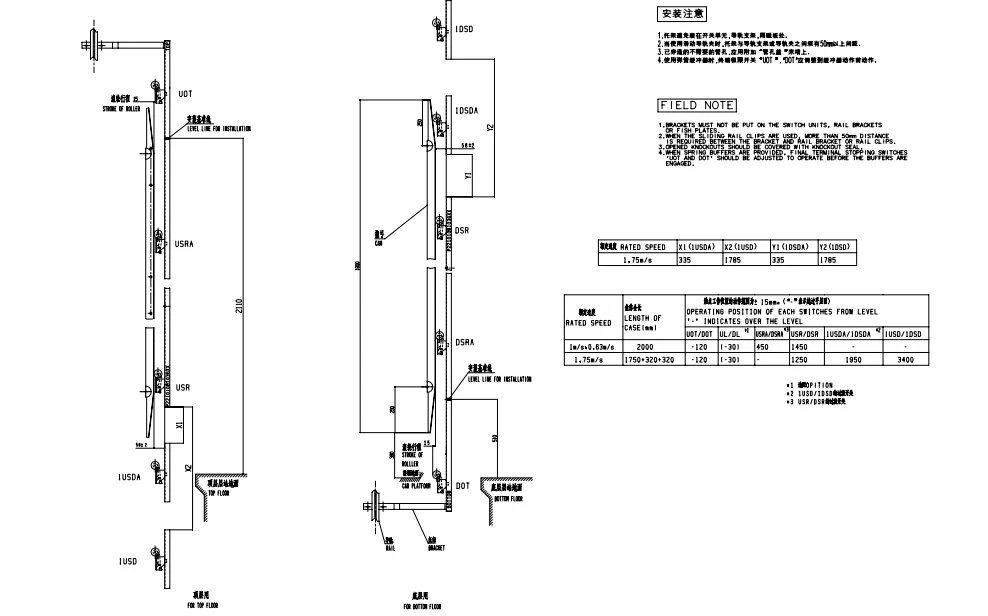
1.2 Terminal Switches
| Type | Function | Safety Level |
|---|---|---|
| Deceleration | Limits car speed near terminals; aids position correction. | Control signal (soft stop). |
| Limit | Prevents overtravel at terminals (e.g., USL/DSL). | Safety circuit (hard stop). |
| Final Limit | Last-resort mechanical stop (e.g., UFL/DFL). | Cuts #5/#LB power. |
Note: Machine-room-less (MRL) elevators may repurpose upper terminal switches as manual operation limits.
2 General Troubleshooting Steps
2.1 Leveling Switch Faults
Symptoms:
-
Poor leveling (±15mm error).
-
Frequent re-leveling or "AST" (Abnormal Stop) faults.
-
Incorrect floor registration.
Diagnostic Steps:
-
PAD Sensor Check:
-
Verify gap between PAD and magnetic vane (5–10mm).
-
Test sensor output with multimeter (DC 12–24V).
-
-
Signal Validation:
-
Use P1 board's debug mode to display PAD signal combinations as the car passes floors.
-
Example: Code "1D" = DZD active; "2D" = DZU active. Mismatches indicate faulty sensors.
-
-
Wiring Inspection:
-
Check for broken/shielded cables near motors or high-voltage lines.
-
2.2 Terminal Switch Faults
Symptoms:
-
Emergency stops near terminals.
-
Incorrect terminal deceleration.
-
Inability to register terminal floors ("write layer" failure).
Diagnostic Steps:
-
Contact-Type Switches:
-
Adjust actuator dog length to ensure simultaneous triggering of adjacent switches.
-
-
Non-Contact (TSD-PAD) Switches:
-
Validate magnet plate sequence and timing (use oscilloscope for signal analysis).
-
-
Signal Tracing:
-
Measure voltage at W1/R1 board terminals (e.g., USL = 24V when triggered).
-
3 Common Faults & Solutions
3.1 Inability to Register Floor Height
| Cause | Solution |
|---|---|
| Faulty Terminal Switch | - For TSD-PAD: Verify magnet plate insertion depth (≥20mm). - For contact switches: Adjust USR/DSR actuator position. |
| PAD Signal Error | Confirm DZD/DZU/RLD/RLU signals reach the control board; check PAD alignment. |
| Board Fault | Replace P1/R1 board or update software. |
3.2 Automatic Terminal Re-Leveling
| Cause | Solution |
|---|---|
| TSD Misalignment | Re-measure TSD installation per drawings (tolerance: ±3mm). |
| Rope Slippage | Inspect traction sheave groove wear; replace ropes if slippage >5%. |
3.3 Emergency Stop at Terminals
| Cause | Solution |
|---|---|
| Incorrect TSD Sequence | Validate magnet plate coding (e.g., U1→U2→U3). |
| Actuator Dog Fault | Adjust length to ensure overlap with limit switches. |
4. Diagrams
Figure 1: PAD Signal Timing
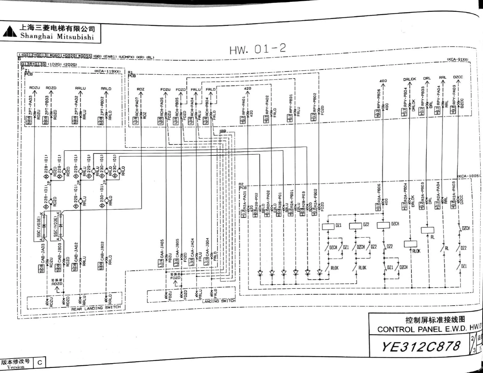
Figure 2: Terminal Switch Layout
Document Notes:
This guide aligns with Mitsubishi elevator standards. For MRL systems, prioritize TSD-PAD magnet plate sequencing checks.
© Elevator Maintenance Technical Documentation


