
Door and Manual Operation Circuit (DR)
1 System Overview
The DR circuit consists of two primary subsystems that govern elevator operation modes and door mechanisms:
1.1.1 Manual/Automatic Operation Control
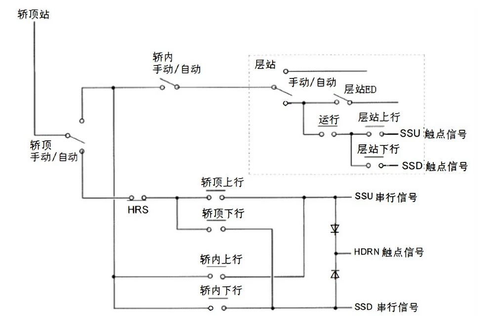
The system implements a hierarchical control structure with clearly defined priority levels:
-
Control Hierarchy (Highest to Lowest Priority):
-
Car Top Station (Emergency Operation Panel)
-
Car Operating Panel
-
Control Cabinet/Hall Interface Panel (HIP)
-
-
Operation Principle:
-
The manual/auto selector switch determines control authority
-
In "Manual" mode, only the car top buttons receive power (disabling other controls)
-
The "HDRN" confirmation signal must accompany all movement commands
-
-
Key Safety Features:
-
Interlocked power distribution prevents conflicting commands
-
Positive verification of manual operation intent (HDRN signal)
-
Fail-safe design defaults to safest condition during faults
-
1.1.2 Door Operation System
The door control system mirrors the main elevator drive system in functionality:
-
System Components:
-
Sensors: Door photocells (analogous to hoistway limit switches)
-
Drive Mechanism: Door motor + synchronous belt (equivalent to traction system)
-
Controller: Integrated drive electronics (replacing separate inverter/DC-CT)
-
-
Control Parameters:
-
Door type configuration (center/side opening)
-
Travel distance settings
-
Speed/acceleration profiles
-
Torque protection thresholds
-
-
Protection Systems:
-
Stall detection
-
Overcurrent protection
-
Thermal monitoring
-
Speed regulation
-
1.2 Detailed Functional Description
1.2.1 Manual Operation Circuit
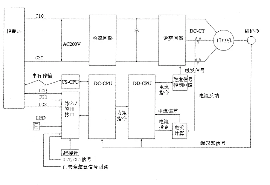
The manual control system employs a cascaded power distribution design:
-
Circuit Architecture:
-
79V control power distribution
-
Relay-based priority switching
-
Optical isolation for signal transmission
-
-
Signal Flow:
-
Operator input → Command verification → Motion controller
-
Feedback loop confirms command execution
-
-
Safety Verification:
-
Dual-channel signal confirmation
-
Watchdog timer monitoring
-
Mechanical interlock verification
-
1.2.2 Door Control System
The door mechanism represents a complete motion control system:
-
Power Stage:
-
Three-phase brushless motor drive
-
IGBT-based inverter section
-
Regenerative braking circuit
-
-
Feedback Systems:
-
Incremental encoder (A/B/Z channels)
-
Current sensors (phase and bus monitoring)
-
Limit switch inputs (CLT/OLT)
-
-
Control Algorithms:
-
Field-oriented control (FOC) for synchronous motors
-
V/Hz control for asynchronous motors
-
Adaptive position control
-
1.3 Technical Specifications
1.3.1 Electrical Parameters
| Parameter | Specification | Tolerance |
|---|---|---|
| Control Voltage | 79V AC | ±10% |
| Motor Voltage | 200V AC | ±5% |
| Signal Levels | 24V DC | ±5% |
| Power Consumption | 500W max | - |
1.3.2 Mechanical Parameters
| Component | Specification |
|---|---|
| Door Speed | 0.3-0.5 m/s |
| Opening Time | 2-4 seconds |
| Closing Force | <150N |
| Overhead Clearance | 50mm min |
1.4 System Interfaces
-
Control Signals:
-
D21/D22: Door open/close commands
-
41DG: Door lock status
-
CLT/OLT: Position verification
-
-
Communication Protocols:
-
RS-485 for parameter configuration
-
CAN bus for system integration (optional)
-
-
Diagnostic Ports:
-
USB service interface
-
LED status indicators
-
7-segment fault display
-
2 Standard Troubleshooting Steps
2.1 Manual Operation from Car Top
2.1.1 Up/Down Buttons Not Functioning
Diagnostic Procedure:
-
Initial Status Check
-
Verify P1 board fault codes and status LEDs (#29 safety circuit, etc.)
-
Consult troubleshooting manual for any displayed fault codes
-
-
Power Supply Verification
-
Check voltage at each control level (car top, car panel, control cabinet)
-
Confirm manual/auto switch is properly positioned
-
Test HDRN signal continuity and voltage levels
-
-
Signal Transmission Check
-
Verify up/down command signals reach P1 board
-
For serial communication signals (car top to car panel):
-
Check CS communication circuit integrity
-
Verify termination resistors
-
Inspect for EMI interference
-
-
-
Priority Circuit Validation
-
Confirm proper isolation of non-priority controls when in manual mode
-
Test relay operation in selector switch circuit
-
2.2 Door Operation Faults
2.2.1 Door Encoder Issues
Synchronous vs. Asynchronous Encoders:
| Feature | Asynchronous Encoder | Synchronous Encoder |
|---|---|---|
| Signals | A/B phase only | A/B phase + index |
| Fault Symptoms | Reverse operation, overcurrent | Vibration, overheating, weak torque |
| Testing Method | Phase sequence check | Full signal pattern verification |
Troubleshooting Steps:
-
Verify encoder alignment and mounting
-
Check signal quality with oscilloscope
-
Test cable continuity and shielding
-
Confirm proper termination
2.2.2 Door Motor Power Cables
Phase Connection Analysis:
-
Single Phase Fault:
-
Symptom: Severe vibration (elliptical torque vector)
-
Test: Measure phase-to-phase resistance (should be equal)
-
-
Two Phase Fault:
-
Symptom: Complete motor failure
-
Test: Continuity check of all three phases
-
-
Phase Sequence:
-
Only two valid configurations (forward/reverse)
-
Swap any two phases to change direction
-
2.2.3 Door Limit Switches (CLT/OLT)
Signal Logic Table:
| Condition | 41G | CLT | OLT Status |
|---|---|---|---|
| Door Closed | 1 | 1 | 0 |
| Door Open | 0 | 1 | 1 |
| Transition | 0 | 0 | 0 |
Verification Steps:
-
Physically confirm door position
-
Check sensor alignment (typically 5-10mm gap)
-
Verify signal timing with door movement
-
Test jumper configuration when OLT sensor absent
2.2.4 Safety Devices (Light Curtain/Edges)
Critical Differences:
| Feature | Light Curtain | Safety Edge |
|---|---|---|
| Activation Time | Limited (2-3 sec) | Unlimited |
| Reset Method | Automatic | Manual |
| Failure Mode | Forces close | Maintains open |
Testing Procedure:
-
Verify obstruction detection response time
-
Check beam alignment (for light curtains)
-
Test microswitch operation (for edges)
-
Confirm proper signal termination at controller
2.2.5 D21/D22 Command Signals
Signal Characteristics:
-
Voltage: 24VDC nominal
-
Current: 10mA typical
-
Wiring: Shielded twisted pair required
Diagnostic Approach:
-
Verify voltage at door controller input
-
Check for signal reflections (improper termination)
-
Test with known good signal source
-
Inspect traveling cable for damage
2.2.6 Jumper Settings
Configuration Groups:
-
Basic Parameters:
-
Door type (center/side, single/double)
-
Opening width (600-1100mm typical)
-
Motor type (sync/async)
-
Current limits
-
-
Motion Profile:
-
Opening acceleration (0.8-1.2 m/s²)
-
Closing speed (0.3-0.4 m/s)
-
Deceleration ramp
-
-
Protection Settings:
-
Stall detection threshold
-
Overcurrent limits
-
Thermal protection
-
2.2.7 Closing Force Adjustment
Optimization Guide:
-
Measure actual door gap
-
Adjust CLT sensor position
-
Verify force measurement (spring scale method)
-
Set holding current (typically 20-40% of max)
-
Confirm smooth operation through full range
3 Door Controller Fault Code Table
| Code | Fault Description | System Response | Recovery Condition |
|---|---|---|---|
| 0 | Communication Error (DC↔CS) | - CS-CPU resets every 1 second - Door emergency stop then slow operation | Automatic recovery after fault clears |
| 1 | IPM Comprehensive Fault | - Gate drive signals cut off - Door emergency stop | Manual reset required after fault clears |
| 2 | DC+12V Overvoltage | - Gate drive signals cut off - DC-CPU reset - Door emergency stop | Automatic recovery after voltage normalizes |
| 3 | Main Circuit Undervoltage | - Gate drive signals cut off - Door emergency stop | Automatic recovery when voltage restored |
| 4 | DC-CPU Watchdog Timeout | - Gate drive signals cut off - Door emergency stop | Automatic recovery after reset |
| 5 | DC+5V Voltage Anomaly | - Gate drive signals cut off - DC-CPU reset - Door emergency stop | Automatic recovery when voltage normalizes |
| 6 | Initialization State | - Gate drive signals cut off during self-test | Completes automatically |
| 7 | Door Switch Logic Error | - Door operation disabled | Requires manual reset after fault correction |
| 9 | Door Direction Error | - Door operation disabled | Requires manual reset after fault correction |
| A | Overspeed | - Emergency stop then slow door operation | Automatic recovery when speed normalizes |
| C | Door Motor Overheat (Sync) | - Emergency stop then slow door operation | Automatic when temperature drops below threshold |
| D | Overload | - Emergency stop then slow door operation | Automatic when load reduces |
| F | Excessive Speed | - Emergency stop then slow door operation | Automatic when speed normalizes |
| 0. to 5. | Various Position Errors | - Emergency stop then slow operation - Normal after door fully closes | Automatic recovery after proper door closure |
| 9. | Z-phase Fault | - Slow door operation after 16 consecutive errors | Requires encoder inspection/repair |
| A. | Position Counter Error | - Emergency stop then slow operation | Normal after door fully closes |
| B. | OLT Position Error | - Emergency stop then slow operation | Normal after door fully closes |
| C. | Encoder Fault | - Elevator stops at nearest floor - Door operation suspended | Manual reset after encoder repair |
| E. | DLD Protection Triggered | - Immediate door reversal when threshold reached | Continuous monitoring |
| F. | Normal Operation | - System functioning properly | N/A |
3.1 Fault Severity Classification
3.1.1 Critical Faults (Require Immediate Attention)
-
Code 1 (IPM Fault)
-
Code 7 (Door Switch Logic)
-
Code 9 (Direction Error)
-
Code C (Encoder Fault)
3.1.2 Recoverable Faults (Auto-reset)
-
Code 0 (Communication)
-
Code 2/3/5 (Voltage Issues)
-
Code A/D/F (Speed/Load)
3.1.3 Warning Conditions
-
Code 6 (Initialization)
-
Code E (DLD Protection)
-
Codes 0.-5. (Position Warnings)
3.2 Diagnostic Recommendations
-
For Communication Errors (Code 0):
-
Check termination resistors (120Ω)
-
Verify cable shielding integrity
-
Test for ground loops
-
-
For IPM Faults (Code 1):
-
Measure IGBT module resistances
-
Check gate drive power supplies
-
Verify proper heatsink mounting
-
-
For Overheat Conditions (Code C):
-
Measure motor winding resistance
-
Verify cooling fan operation
-
Check for mechanical binding
-
-
For Position Errors (Codes 0.-5.):
-
Recalibrate door position sensors
-
Verify encoder mounting
-
Check door track alignment
-


