
Brake Circuit (BK)
1 Overview
Brake circuits Are categorized into two types: current-controlled and resistive voltage divider-controlled. Both consist of drive circuits and contact feedback circuits.
1.1 Current-Controlled Brake Circuit
-
Structure:
-
Drive Circuit: Powered by #79 or S420, controlled via #LB contactor.
-
Feedback Circuit: Brake contact signals (open/closed) sent directly to W1/R1 boards.
-
-
Operation:
-
#LB contactor closes → Control unit (W1/E1) activates.
-
Control unit outputs brake voltage → Brake opens.
-
Feedback contacts transmit armature status.
-
Schematic: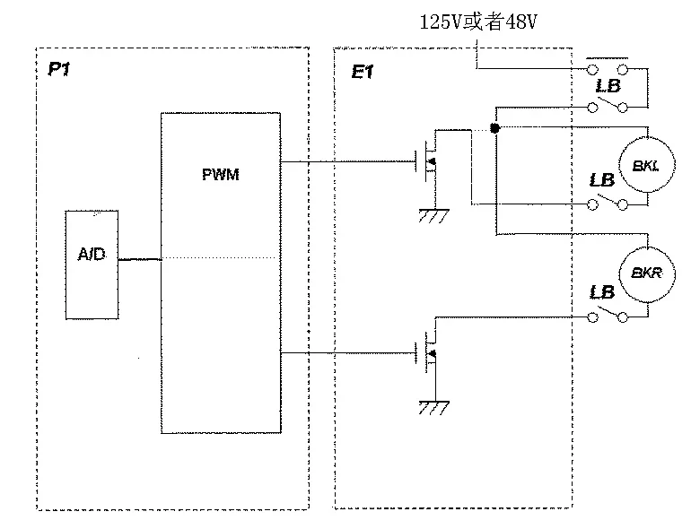
1.2 Resistive Voltage Divider-Controlled Brake Circuit
-
Structure:
-
Drive Circuit: Includes voltage-dividing resistors and feedback contacts.
-
Feedback Circuit: Monitors armature position via NC/NO contacts.
-
-
Operation:
-
Brake Closed: NC contacts short-circuit resistors → Full voltage applied.
-
Brake Open: Armature moves → NC contacts open → Resistors reduce voltage to maintenance level.
-
Enhanced Feedback: Additional NO contacts verify brake closure.
-
Key Note:
-
For ZPML-A traction machines, brake gap adjustment directly affects armature travel (optimal: ~2mm).
2 General Troubleshooting Steps
2.1 Brake Action Failures
Symptoms:
-
Brake fails to open/close (single or both sides).
-
Note: Complete brake failure may cause car slippage (critical safety hazard).
Diagnostic Steps:
-
Check Voltage:
-
Verify full voltage pulse during opening and maintenance voltage afterward.
-
Use multimeter to measure coil voltage (e.g., 110V for #79).
-
-
Inspect Contacts:
-
Adjust contact alignment (center for current control; near travel end for resistive control).
-
-
Mechanical Checks:
-
Lubricate linkages; ensure no obstructions in armature path.
-
Adjust brake gap (0.2–0.5mm) and torque spring tension.
-
2.2 Feedback Signal Faults
Symptoms:
-
Brake operates normally, but P1 board shows brake-related codes (e.g., "E30").
Diagnostic Steps:
-
Replace Feedback Contacts: Test with known-good components.
-
Adjust Contact Position:
-
For resistive control: Align contacts near armature travel end.
-
-
Check Signal Wiring:
-
Verify continuity from contacts to W1/R1 boards.
-
2.3 Combined Faults
Symptoms:
-
Brake action failure + fault codes.
Solution:
-
Perform full brake adjustment using tools like ZPML-A Brake Calibration Device.
3 Common Faults & Solutions
3.1 Brake Fails to Open
| Cause | Solution |
|---|---|
| Abnormal Coil Voltage | Check control board output (W1/E1) and wiring integrity. |
| Misaligned Contacts | Adjust contact position (follow ZPML-A guidelines). |
| Mechanical Blockage | Clean/lubricate brake arms; adjust gap and spring tension. |
3.2 Insufficient Braking Torque
| Cause | Solution |
|---|---|
| Worn Brake Linings | Replace linings (e.g., ZPML-A friction pads). |
| Loose Torque Spring | Adjust spring tension to specifications. |
| Contaminated Surfaces | Clean brake discs/pads; remove oil/grease. |
4. Diagrams
Figure : Brake Circuit Schematics
-
Current Control: Simplified topology with independent drive/feedback paths.
-
Resistive Control: Voltage-dividing resistors and enhanced feedback contacts.
Document Notes:
This guide aligns with Mitsubishi elevator standards. Always follow safety protocols and consult technical manuals for model-specific details.
© Elevator Maintenance Technical Documentation


