
1. Basic Main Interface BoArd - SMIC5R.Q
① Main interface controller board
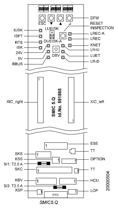
② LED
| LED | Normal Display | Explanation |
| LUEISK | OFF | ON = Safety circuit power OFF (Red LED on DUEISK-A) (Reasons: Safety circuit start voltage > 55V or < 20V, safety circuit end voltage > 29V, safety circuit current > 1A) |
| IUSK | ON | ON = Safety circuit power supply 24...55 VDC normal |
| ISPT | ON | ON = Pit safety circuit closed |
| RTS | ON | ON = Pit and hall door safety circuit closed |
| ISK | ON | ON = Safety circuit fully closed |
| 24V | ON | ON = 24VDC available from SNGL1.Q |
| 5V | ON | ON = VCC 5VDC (logic power supply) available, converted from 24VDC on SMIC5.Q |
| BBUS | Flashing | Flashing = BIO bus activated |
| LR-U | ON/OFF | ON = Car moving upwards (feedback from ACVF) |
| LUET | ON/OFF | ON = Car position within the door zone |
| LR-D | ON/OFF | ON = Car moving downwards (feedback from ACVF) |
| KNET | ON/OFF | LED KNET permanently on or off |
③ Fuse
| Fuse | Description |
| SI1 | 24 VDC power supply for SDIC (2.5 AT) |
| SI2 | 24 VDC power supply for BIO bus (2.5 AT) |
④ Button
| Button | Description |
| DUEISK-A | The safety circuit power switch is restarted (after LUEISK is activated). |
| RESET INSPECTION | Function 1: The car automatically positions itself to enter the top of the car. |
| DBV | The remote trigger of the GBV speed limiter during the acceptance testing process. |
⑤ Plug configuration
| Plug | Description |
| XIC_ Right / Left | To the SCIC5.Q interface |
| ESE | ESE or jumper BESE |
| SKS | Shaft safety circuit (and option KNET) |
| TT (RJ11) | Servitel TM4 GTM (Single ladder without line manager) |
| TT | Telephone line; external T+T or TM4 line manager or GSV |
| KSS | Safety circuit slack rope contact |
| Options | Backup alarm contactor SOA and LAS |
| SKC | Main connection to the car (safety circuit, power supply 24 VDC and 12 VDC, CAN bus) |
| KBV | GBP safety circuit, MGBV, (KFG) |
| HCU | Automatic Evacuation Unit (HCU) |
| XSP | To Intercom's 12V-NSG (Pin 1 = 12VDC, Pin 2 = GND) |
| LOP | External network devices for the station include LOP/LIN/LCUX (BIO bus). |
| SNGL | Connection to SNGL PCB (PEBO) |
2. Microprocessor PCB SCIC 51.Q
① Control Cabinet Interface Controller
• SCIC51.Q has a larger EEPROM (AP version)
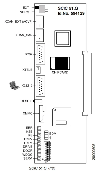
② The significance of LED
| LED | Normal display | Description | Notes |
| ERR | OFF | ON = Critical Fault Flashing = Warning | Automatic reset required for manual reset |
| KSE | ON/OFF | KSE state ON = within KSE range | This feature is not supported (remains disabled) in actual software. |
| KS | ON/OFF | PHS Status | ON = Located in the PHS area |
| TRIP2 | OFF | ON = Maintenance mode activated | ON = DIP switch S7 Turns on or enters special mode 104 |
| TRIP1 | OFF | ON = Weighing disabled; Flashing light = Weighing system malfunction. | ON = DIP switch S1 turns on or enters special mode 107 (HMI). |
| Drive | OFF | Flickering = Drive system malfunction | Attempt ACVF fatal fault reset, special mode 101 (HMI) |
| Door | OFF | Flickering = Gate system malfunction | |
| WDOG | Flashing | If the software is working properly, it will flash once every 2 seconds. | |
| SERV. | OFF | Installation and running mode | ON = DIP switch S8 is open |
③ Button
| Button | Description |
| Reset | Manual reset |
④ DIP switch
| DIP S1 | Description | Notes |
| 1 | ON = Weighing unit off | LED "TRIP1" is open. |
| 2 | Unused | |
| 3 | ON = XTELE enables connection to the service PC. | Communicating with the service PC |
| 4 | Unused | Four-digit fault indication on COP5 |
| 5 | Unused | |
| 6 | Configuration mode combined with COP5 | |
| 7 | ON = Maintenance Mode | LED "TRIP2" is open. |
| 8 | Installation and Run Mode (also used for learning run and fatal failure reset) | LED "SERV." is open. |
⑤ Other switches
| Switch | Description | Notes |
| CAN bus terminal | For bus termination, if no device is connected to the EXT port of the CAN bus, set the switch to the "NORM" position. | Normal position: "EXT." |
⑥ Jumper
| Jumper | Description | Notes |
| BDM | Debugger interface | Do not use it! |
⑦ Plug configuration
| Description | Notes | |
| XCAN-EXT | CAN bus to ACVF | |
| XCAN-CAR | CAN bus (SDIC) to the car | "SKC" Plug |
| X232 | Connection of parallel ladders | |
| XTELE | Servitel TM4 Remote Monitoring (GTM) | Can be used for service PC (SCIC DIP switch 3) |
| X232_2 | Service PC connection | Terminal program (software version ≥ 9.2 CADI GC) |
| XMMC | MMC Multimedia Card Interface | Software update SCIC |
| CHIPCARD | The chip card includes elevator options and ACVF parameters. |
3. Power Supply Board - SNGL2.Q
①Elevator Power Supply
• 24V power supply, 12V emergency power supply
• Manual evacuation PEBO (Electronic Pulse Brake Opening)
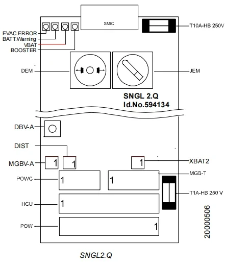
② LED
| LED | Normal Display | Explanation |
| EVAC.ERROR | OFF | OFF = Normal mode; |
| BATT. Warning | OFF | ON = Remaining battery voltage <= 10% |
| VBAT | ON | ON = Battery voltage exists |
| BOOSTER | OFF/ON | OFF = Normal mode, ON = Regulator can provide 120 VDC output voltage Only effective when DEM is pressed in manual evacuation mode. |
③ Fuse
| Fuse | Description |
| T10A-HB 250V | PEBO's internal protection (10 AT) |
| T10A-HB 250V | 12 VDC emergency power supply output protection (1 AT) |
④ Button
| Button | Description |
| DBV-A | Remote reset of speed limiter |
⑤ Plug configuration
| Plug | Description |
| SMIC | Connections to SMIC (power supply, safety circuit, KBV, fuse, LUET) |
| POWC | Power supply for car doors and car lights |
| MGB-T | Two test connectors (Test-MGB/Test-MGB1) are required for the "single-sided brake capability test" (single disc brake test). |
| MCU | Power supply from/to SHCU and MGBs (without SHCU: jumper required). |
| POW | Power supply from SIS and to/from transformer TS |
| BAT2 | Emergency power supply battery |
| DIST | Distance sensor |
| MGBC-A | Power supply to the speed limiter coil |
⑥ Manual evacuation interface
| Description | Notes | |
| JEM | Manual evacuation switch. Counter-clockwise position = Manual evacuation activated. | JEM = Enabled to prevent other types of operation (safety loop interruption). |
| DEM | Manual Evacuation Button | The brake is opened for a predetermined time (pulse). |
4. Hall/Station Input/Output Board - SLCUX1.Q
① External Call Unit Expansion Card
Main Functions:
• Connects additional inputs and outputs within the hoistway
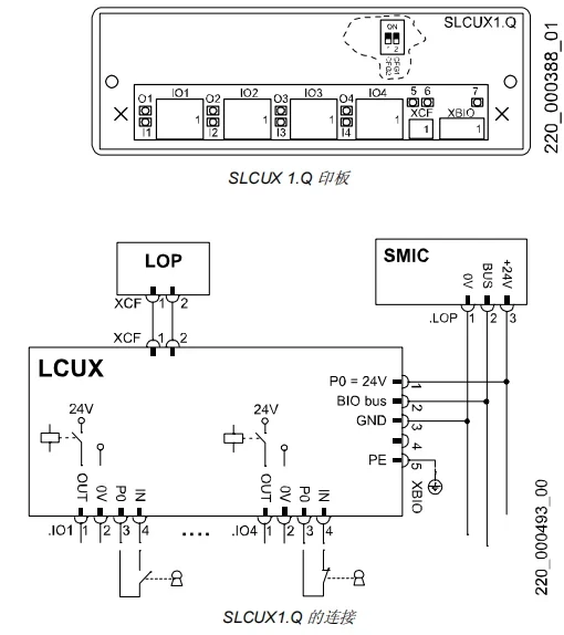
② Plug configuration
| Plug | Description | Notes |
| XBIO | BIO bus | |
| XCF | Synchronous | Connection to LCU(M) or LOP |
| IO1..IO4 | Input / Output | Input: Pins 3-4 Output: Pins 1-2 (P0, maximum 0.4 A) |
③ LEDs on the SLCUX1.Q PCB board
| LED | Normal operation | Notes |
| O1 .. O4 | ON/OFF | ON = Output active (depending on BMK settings) |
| I1 .. Ich | ON/OFF | ON = Input activated (contact closed) |
| 5 | Blinking | Watchdog |
| 6 | OFF | ON = Output current overload |
| 7 | ON | P0 is powered by the BIO bus. |
④ DIP switch settings
| DIP 1 CFG2 | DIP 2 CFG1 | Node Definition and Configuration Menu |
| ON | ON | LCUX defaults to the address of "Node 1". CF=87 |
| ON | OFF | LCUX defaults to the address of "Node 2". CF=88 |
| OFF | ON | LCUX defaults to the address of "Node 3". CF=89 |
| OFF | OFF | LCUX address not determined |
Note 1: If the LCUX is connected to a floor's LOP, its fixed address will be overwritten by a new address when that LOP is configured. (This is independent of the actual DIP switch settings.)
Note 2: If an address is assigned to the LCUX when the LOP is configured, it can recover its fixed address with the help of CF=94.
Note 3: The LCUX's fixed address has not yet been released.
4. Fermator Compact VVVF4+ Door Drive
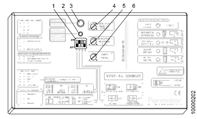
① DIP switch settings
| Normal position | Notes | ||
| 1 | Enter 1 and 2 | OFF | ON = Enter 1 (On/Off) OFF = Enter 2 |
| 2 | Hall door type | ON | ON = Automatic door OFF = Manual door |
| 3 | The door opened | ON/OFF | ON = Left side open (TL) OFF = Right side open (TR) or middle open |
| 4 | Master and Slave | OFF | ON = Master OFF = Slave |
Note regarding door opening: The setting for DIP switch 3 varies depending on the Fermator VVVF4 control box model (and some older diagrams may be incorrect).
→ For correct setting, please refer to the label on the control box!
Note regarding DIP switches: The location of the DIP switches may not be easily visible. The DIP switches on new control boxes are black. Check the location by turning the DIP switches on and off.
② Debugging process
| 1 | Ensure all plugs are correctly connected. The car and landing doors must be properly connected. |
| 2 | Open the door drive (on the Fermator VVVF4 control box side) |
| 3 | Press the "Auto Adjust" button (2) |
| 4 | The test button (3) can be used to test the operation. |
| 5 | Check the safety function of the force limiter. If necessary, adjust it to less than 150N using a potentiometer (6). |
| 6 | If necessary, adjust the opening speed (5) and closing speed (4). |


