
1.LEHY series elevators with machine room, applicable to UCMP models: ZBK-PMN, ZBK-PMR, ZBK-PMS, ZBK-PMI, ZBK-PMP, ZBK-PMU, ZBK-PMD, ZBK-PME.
1.1 Verification of Lifting or releasing of the brake mechanism.
1.1.1 Verify elevator
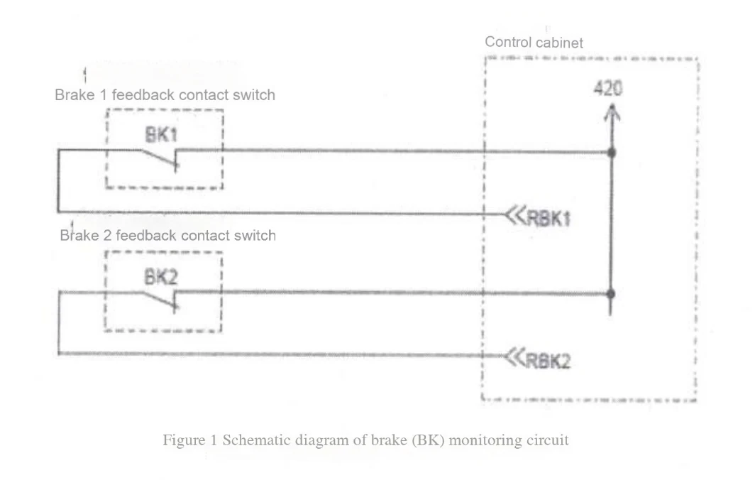
The brake feedback contact switch independently monitors the release and engagement of each brake. The contact switch uses a normally closed contact. When the brake is released, the normally closed contact is disconnected and the brake detection circuit is disconnected. The brake detection circuit schematic diagram 1 is shown (taking a double brake as an example)
1.1.2 Verification method and steps
1.1.2.1 Detecting brake OFF fault (failure to release the brake)
(1) The elevator stops running and confirms that the door is completely closed;
(2) Cut off the elevator power supply and short-circuit the normally closed contact switch of brake 1 (BK1);
(3) Power on and stArt the elevator automatically;
(4) The elevator detects the brake 1 OFF fault as soon as it starts, and the elevator stops suddenly;
(5) The brake 1 OFF fault is detected four times in a row, and the elevator cannot be started again;
(6) Cut off the elevator power supply, remove the short circuit and clear the latch fault; then power on to restore the elevator to normal;
(7) Follow the same steps as (1) to (6) to test the remaining brake switch OFF faults.
1.1.2.2 Detecting the brake ON fault (failure to hold the brake)
(1) Stop the elevator and confirm that the door is completely closed;
(2) Cut off the elevator power supply and disconnect the brake 1 normally closed contact switch (BK1) detection circuit;
(3) Power on, the elevator detects the brake 1 ON fault and should not be able to start again;
(4) Confirm that the elevator cannot be started and operated through normal automatic operation at this time;
(5) Cut off the elevator power supply, restore the brake contact switch detection circuit and clear the latch fault; then power on to restore the elevator to normal;
(6) Follow the same steps as (1) to (5) to test the remaining brake switch ON faults.
1.2 Braking torque confirmation
1.2.1 Braking torque confirmation steps
(1) Park the car at the top door area in normal mode;
(2) Confirm that the car is unloaded;
(3) Switch the operation mode from normal to emergency electric mode (turn the "normal/emergency electric operation" switch on the emergency electric operation device to the "emergency electric operation" side, and separate the "EDSW" connector on the device connection cable):
(4) Adjust the rotary potentiometer SET1 on the P1 board to 0, SETO to 8, and press SW1 downward;
(5) Adjust the rotary potentiometer MONI on the P1 board to 0, MONO to 5;
(6) Close the elevator door and run it down from the top floor for about 600mm until the DZ light on the P1 board is off;
(7) Switch the operation mode =Mode, switch from emergency electric mode to normal mode (turn the "normal/emergency electric operation" switch on the emergency electric operation device to the "normal" side, and connect the "EDSW" connector on the device connection cable);
(8) The elevator automatically returns to the top door area at low speed and stops at the top door area. At this time, the digital tube on the P1 board displays the maximum speed of low-speed operation;
(9) Wait for about 10 seconds, and the elevator door opens;
(10) Quickly switch the operation mode from normal to emergency electric mode again (turn the "normal/emergency electric operation" switch on the emergency electric operation device to the "emergency electric operation" side, and separate the "EDSW" connector on the device connection cable);
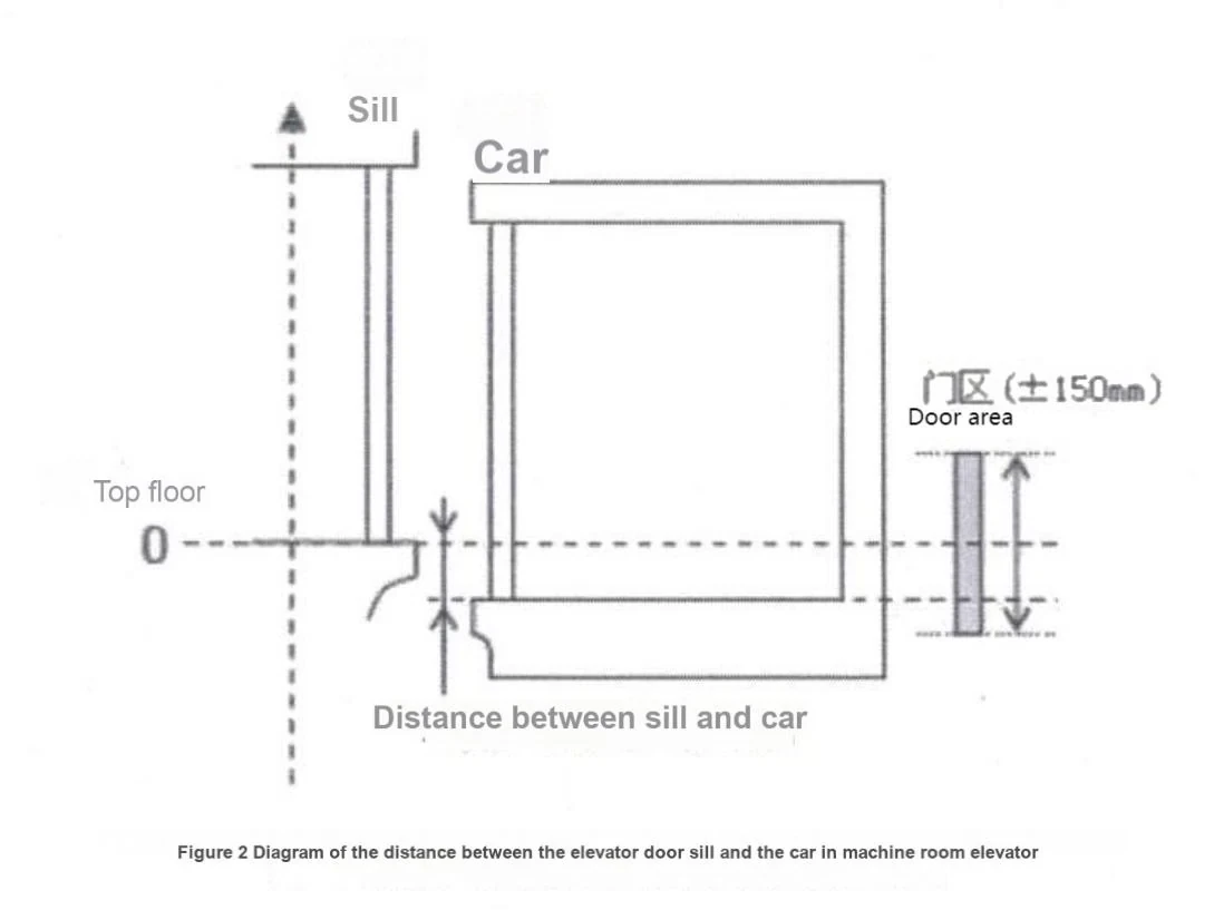
(11) Measure the distance X between the car and the floor door sill and record it. When the car sill is lower than the floor door sill, X takes a positive value. If the car sill is higher than the floor door sill, X takes a negative value (see Figure 2);
(12) Calculate the stopping distance according to the following formula: S=150-X(mm)
(13) Repeat steps (6) to (12) five times;
(14) Restore the rotary potentiometer settings, adjust MON1 on the P1 board to 0, MONO to 8, and press SWI down;
(15) In the emergency electric operation mode, reset the elevator or power off and then power on to clear the latched fault.
(16) Switch the operation mode from emergency electric to normal mode (turn the "Normal/Emergency Electric Operation" switch on the emergency electric operation device to the "Normal" side, and connect the "EDSW" connector on the device connection cable) to restore the elevator to normal.
1.2.2 Braking torque confirmation method
Calculate the average of the braking distances measured 5 times and confirm it according to the UCMP model. It should be less than the corresponding braking distance value in Table 3; otherwise, it means that the braking force is insufficient and repair and maintenance should be carried out until the test meets the requirements again.
| Table 1 Braking and stopping distances of LEHY series elevators with machine room | |||||
| Traction model | UCMP Model | Testing agency | Test speed for final inspection (m/s) | Corresponding stopping distance value (m) | |
| ZPML-J117 | ZBK-PMN | ETC | 0.3 | 0.5 | |
| ZPML-J193 | ZBK-PMR | ETC | 0.3 | 0.5 | |
| ZPML-J183/ ZPML-J248 | ZBK-PMS | ETC | 0.3 | 0.5 | |
| ZPML-C400A | ZBK-PMI | ETC | 0.3 | 0.5 | |
| ZPML-H280 | ZBK-PMP | ETC | 0.3 | 0.5 | |
| ZPML-G960 | ZBK-PMU | ETC | 0.3 | 0.5 | |
| ZPML-A075/ ZPML-A067/ ZPML-A117/ ZPML-A133 | ZBK-PMD | ETC | 0.3 | 0.5 | |
| ZPML-A157 | ZBK-PME | ETC | 0.3 | 0.5 | |
2 LEHY-MRL series elevators, applicable UCMP models: ZBK-PMW, ZBK-PMQ, ZBK-PMAC, ZBK-PMZ
2.1 Verification of lifting or releasing of brake mechanism
Same as 1.1
2.2 Braking torque confirmation
2.2.1 Braking torque confirmation steps
(1) Park the car at the top door area in normal mode;
(2) Confirm that the car is unloaded;
(3) Switch the switch in the HIP device to the emergency electric operation position;
(4) Adjust the rotary potentiometer SET1 on the HIP board to 0, SETO to 8, and press SW1 downward;
(5) Adjust the potentiometer MON1 to 0 and MON0 to 5;
(6) Close the elevator door and run it down from the top floor for about 600 mm until the DZ light in the HIP device turns off;
(7) Switch the "Emergency Electric Operation" switch in the HIP device to the normal position:
(8) The elevator automatically returns to the top door area at a low speed and stops at the top door area. At this time, the digital tube on the HIP board displays the maximum speed of low-speed operation;
(9) Wait for about 10 seconds, and the elevator door opens;
(10) Quickly switch the HIP board switch to the emergency electric operation position again;
(11) Measure the distance X between the car and the door sill and record it. When the car sill is lower than the floor door sill, X takes a positive value. If the car sill is higher than the floor door sill, X takes a negative value (see Figure 2);
(12) Calculate the stopping distance according to the following formula: S=150-X(mm)
(13) Repeat steps (6)-(12) five times;
(14) Restore the rotary potentiometer settings, adjust MON1 on the P1 board to 0, MON0 to 8, and press SW1 down;
(15) In the emergency electric operation state, reset the elevator or power off and then power on to clear the latched fault;
(16) Switch the switch in the HIP device back to the normal position to restore the elevator to normal.
2.2.2 Braking torque confirmation method.
Calculate the average of the braking distances measured 5 times and confirm it according to the UCMP model. It should be less than the corresponding braking distance value in Table 2; otherwise, it means that the braking force is insufficient and repair and maintenance should be carried out until the test meets the requirements again.
| Table 2 Braking and stopping distances of LEHY series elevators with machine room | |||||
| Traction model | UCMP Model | Testing agency | Test speed for final inspection (m/s) | Corresponding stopping distance value (m) | |
| ZPML-K172 | ZBK-PMN | ETC | 0.3 | 0.5 | |
| ZPML-K268 | ZBK-PMQ | ETC | 0.3 | 0.5 | |
| SSE-160E | ZBK-PMAC | ETC | 0.3 | 0.5 | |
| ZPML-N113 | ZBK-PMZ | NETEC | 0.3 | 0.35 | |
3 HOPE-II, HOPE-IIG, CIC-V series elevators with machine room - applicable UCMP models: ZBK-RGA, ZBK-RGB
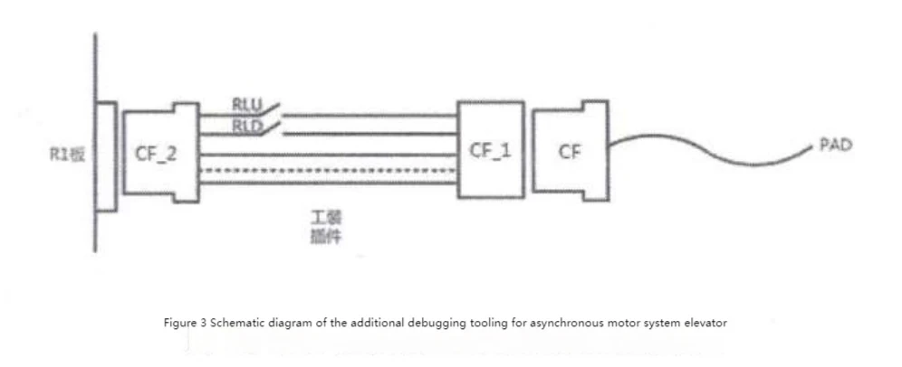
3.1 Power off the control cabinet (disconnect circuit breaker F01), and connect the debugging tool (P295057C000G02) in series to the circuit from PAD to the control cabinet:
3.2 Power on the control cabinet (turn on circuit breaker F01);
3.3 Run the elevator normally to other floors except the top (bottom) floor:
3.4 Run the elevator normally to the top (bottom) floor again;
Tip: It is recommended to test on the top (or bottom) floor.
3.5 When the elevator stops, the door opens automatically and the door is in the open state (the P¹ board 41DG light is off), disconnect the RLU (RLD) signal through the "RLU (RLD)" switch on the debugging tool or the "RLU (RLD)" connector on the control cabinet loop harness: At this time, the re-leveling function will be triggered and the elevator will automatically move upward (downward) for re-leveling. After running for about 10mm, the UCMP protection is triggered and the elevator stops suddenly;
3.6 Confirm that the ZFS-ELE100 has the fault code "FI", and the P¹ board has the UCM action fault code "90b";
3.7 Turn the "normal/emergency electric operation" switch on the emergency electric operation device to the "emergency electric operation" side, and separate the "EDSW" connector on the device connection cable;:
Warning: To prevent the car from moving, the operation mode switch must be completed according to step 7 before performing subsequent operations!
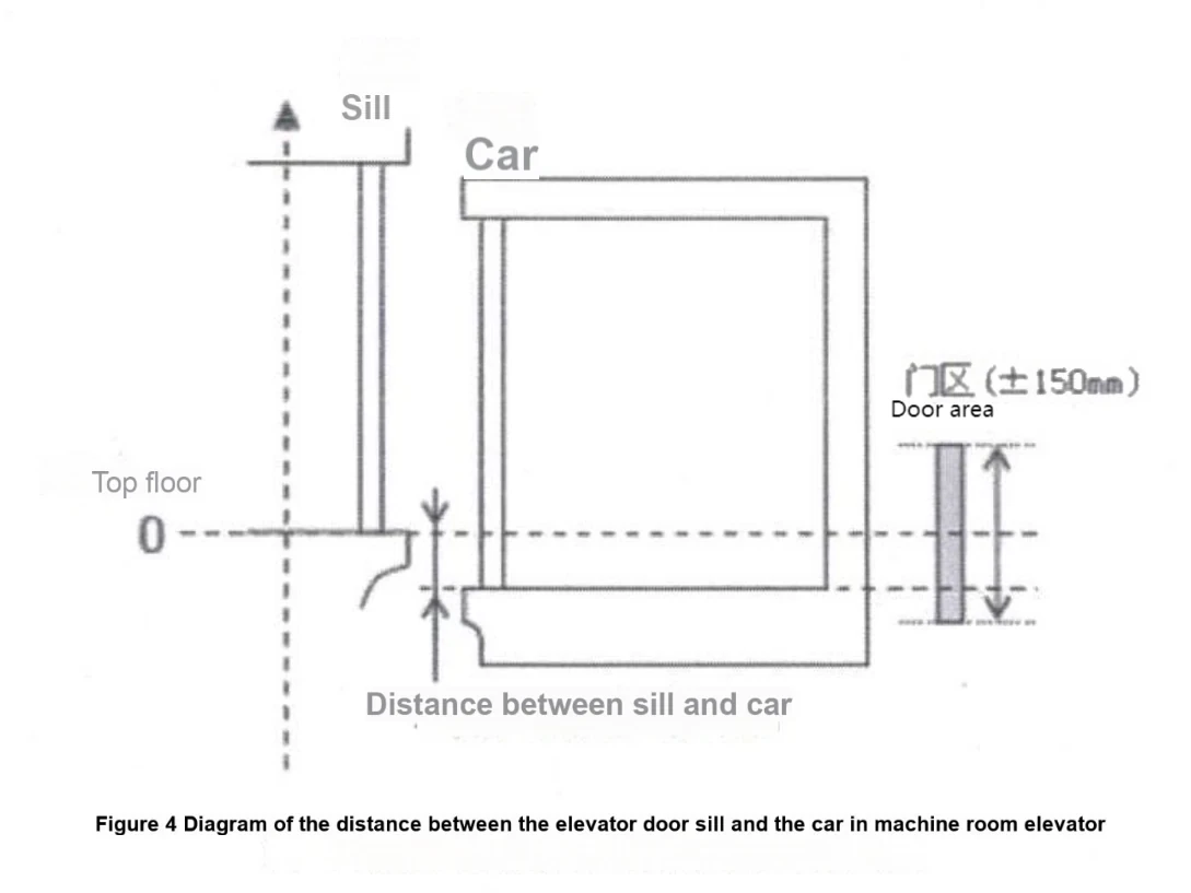
3.8 Measure the distance X between the car door sill and the test floor door sill (see Figure 4); calculate the stopping distance according to the following formula: S=X-10(mm)
Note: There is a height difference between the car sill and the floor station sill, and tripping should be prevented when entering and exiting the car.
9. Power off the control cabinet (disconnect circuit breaker F01) and reconnect the RLU (RLD) signal;
10. In the emergency electric operation mode, power on the control cabinet (close circuit breaker F01). After the P1 board is reset, turn the "Normal/Emergency Electric Operation" switch on the emergency electric operation device to "Normal" and connect the "EDSW" connector on the device connection cable; at this time, the system is reset and the fault in the ZFS-ELE100 device is cleared:
11. Repeat steps (3)-(10) for 5 times:
12. After the test, power off the control cabinet (disconnect circuit breaker F01), remove the debugging tooling, and restore the normal wiring of the elevator.
13. Calculate the average value of the braking distance measured 5 times and confirm that it should be less than the corresponding braking distance value in Table 9; otherwise, it means that the braking force is insufficient and it should be repaired and maintained until the test meets the requirements again.
| Table 3 Braking and stopping distance of HOPE-II, HOPE-IIG and CIC-V series elevators with machine room | |||||
| Traction model | UCMP Model | Testing agency | Test speed for final inspection (m/s) | Corresponding stopping distance value (m) | |
| EM-2400 series | ZBK-RGA | NETEC | 0.067 | 0.235 | |
| EM-3600 series EMJ-500 series | ZBK-RGB | NETEC | 0.067 | 0.175 | |


