
1 Overview
The MC circuit consists of three pArts: input section, main circuit section, and output section.
Input Section
-
Starts from the power input terminals.
-
Passes through EMC components (filters, reactors).
-
Connects to the Inverter module via control contactor #5 (or rectifier module in energy regeneration systems).
Main Circuit Section
-
Core components include:
-
Rectifier: Converts AC to DC.
-
Uncontrolled Rectifier: Uses diode bridges (no phase sequence requirement).
-
Controlled Rectifier: Uses IGBT/IPM modules with phase-sensitive control.
-
-
DC Link:
-
Electrolytic capacitors (series-connected for 380V systems).
-
Voltage-balancing resistors.
-
Optional regeneration resistor (for non-regenerative systems to dissipate excess energy).
-
-
Inverter: Converts DC back to variable-frequency AC for the motor.
-
Output phases (U, V, W) pass through DC-CTs for current feedback.
-
-
Output Section
-
Starts from the inverter output.
-
Passes through DC-CTs and optional EMC components (reactors).
-
Connects to the motor terminals.
Key Notes:
-
Polarity: Ensure correct "P" (positive) and "N" (negative) connections for capacitors.
-
SNUBBER Circuits: Installed on IGBT/IPM modules to suppress voltage spikes during switching.
-
Control Signals: PWM signals transmitted via twisted-pair cables to minimize interference.
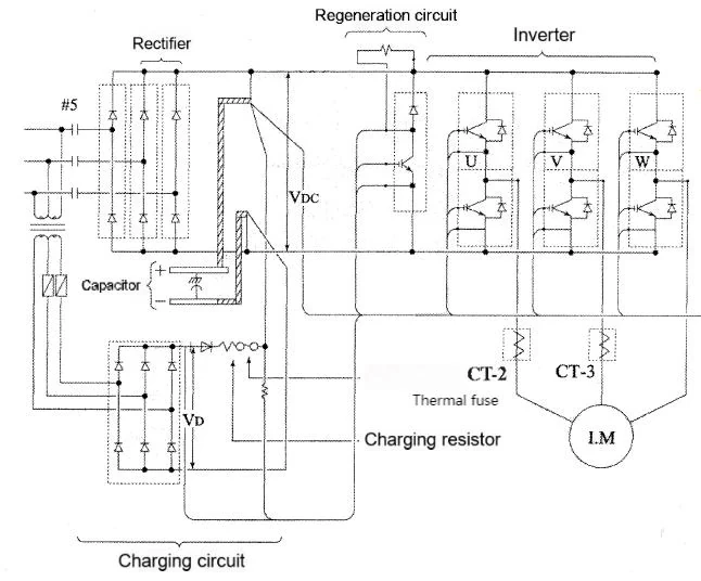
Figure 1-1: Uncontrolled Rectifier Main Circuit
2 General Troubleshooting Steps
2.1 Principles for MC Circuit Fault Diagnosis
-
Symmetry Check:
-
Verify all three phases have identical electrical parameters (resistance, inductance, capacitance).
-
Any imbalance indicates a fault (e.g., damaged diode in rectifier).
-
-
Phase Sequence Compliance:
-
Follow wiring diagrams strictly.
-
Ensure control system phase detection aligns with the main circuit.
-
2.2 Opening Closed-Loop Control
To isolate faults in closed-loop systems:
-
Disconnect Traction Motor:
-
If the system operates normally without the motor, the fault lies in the motor or cables.
-
If not, focus on the control cabinet (inverter/rectifier).
-
-
Monitor Contactor Actions:
-
For regenerative systems:
-
If #5 (input contactor) trips before #LB (brake contactor) engages, check the rectifier.
-
If #LB engages but issues persist, check the inverter.
-
-
2.3 Fault Code Analysis
-
P1 Board Codes:
-
E.g., E02 (overcurrent), E5 (DC link overvoltage).
-
Clear historical faults after each test for accurate diagnosis.
-
-
Regenerative System Codes:
-
Check phase alignment between grid voltage and input current.
-
2.4 (M)ELD Mode Faults
-
Symptoms: Sudden stops during battery-powered operation.
-
Root Causes:
-
Incorrect load weighing data.
-
Speed deviation disrupting voltage balance.
-
-
Check:
-
Verify contactor actions and output voltage.
-
Monitor P1 board codes before (M)ELD shutdown.
-
2.5 Traction Motor Fault Diagnosis
| Symptom | Diagnostic Approach |
|---|---|
| Sudden Stops | Disconnect motor phases one by one; if stops persist, replace motor. |
| Vibration | Check mechanical alignment first; test motor under symmetric loads (20%–80% capacity). |
| Abnormal Noise | Differentiate mechanical (e.g., bearing wear) vs. electromagnetic (e.g., phase imbalance). |
3 Common Faults & Solutions
3.1 PWFH(PP) Indicator Off or Flashing
-
Causes:
-
Phase loss or incorrect sequence.
-
Faulty control board (M1, E1, or P1).
-
-
Solutions:
-
Measure input voltage and correct phase order.
-
Replace the defective board.
-
3.2 Magnetic Pole Learning Failure
-
Causes:
-
encoder misalignment (use dial indicator to check concentricity).
-
Damaged encoder cables.
-
Faulty encoder or P1 board.
-
Incorrect parameter settings (e.g., traction motor configuration).
-
-
Solutions:
-
Reinstall encoder, replace cables/boards, or adjust parameters.
-
3.3 Frequent E02 (Overcurrent) Fault
-
Causes:
-
Poor module cooling (clogged fans, uneven thermal paste).
-
Brake misadjustment (gap: 0.2–0.5mm).
-
Defective E1 board or IGBT module.
-
Motor winding short-circuit.
-
Faulty current transformer.
-
-
Solutions:
-
Clean fans, reapply thermal paste, adjust brakes, or replace components.
-
3.4 General Overcurrent Faults
-
Causes:
-
Driver software mismatch.
-
Asymmetric brake release.
-
Motor insulation failure.
-
-
Solutions:
-
Update software, synchronize brakes, or replace motor windings.
-
Document Notes:
This guide aligns with Mitsubishi elevator technical standards. Always follow safety protocols and refer to official manuals for model-specific details.
© Elevator Maintenance Technical Documentation


