
1. Fan Test
► Check the operation of the motor and Inverter fans:
– Log in to SMLCD.
– Scroll to TESTS → VF TESTS → FAN TEST → OK → OK.
– Now, the fan on the inverter and the fan on the motor (if present) will be running. Listen to all the running fans (if it's a small machine room, perform a visual inspection and ensure all fans Are running).
– The SMLCD displays a "SUCCESS" message.
2. Alarm filtering disable test
► Log in to SMLCD.
► Select the menu Commands → Disable Alarm Filter → ON → OK.
► To enable alarm filtering, use Commands → Disable Alarm Filter → OFF → OK.
3. PEBO is running.
► Ensure the elevator car is empty.
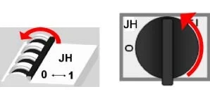
► Set the main power switch (JH) to OFF.
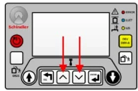
► Simultaneously press and briefly hold the SMLCD "UP" and "DOWN" buttons, and observe the LUET LED indicator light. If the indicator light is "OFF," turn off the control cabinet (AS) and then contact emergency maintenance/elevator service personnel.
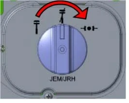
► If both the LUET and the display are active, set the manual evacuation switch (JEM) to the "EVACUATION" position.
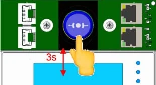
► Press the Manual Evacuation Button (DEM) for 3 seconds. The elevator will move up or down.
► Repeat this process until the LUET LED indicator lights up and the elevator stops moving.
Note:
If the elevator car does not move during each drive attempt due to being in a balanced state, please refer to instructions J 41112041 - S5500 Evacuation Instructions.
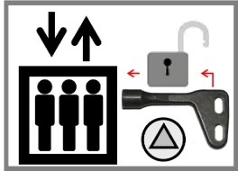
► Lock the control cabinet door.
► Go to the landing door entrance closest to the elevator car.
► Use the special triangular key to manually open the landing door.
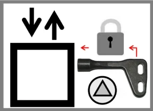
► Close the hall door and make sure it is locked.
4. Braking test at VKN speed
Perform the following tests:
► Normal braking test with an empty car during upward travel.
► Single-sided braking test with an empty car during upward travel.
Prerequisites:
► The elevator should be in normal operating mode.
► When performing braking tests with one brake shoe disabled, prepare the brake and brake control circuit accordingly.
Procedure
Note:
The braking test with an empty elevator car must be performed twice.
First Test
► Position the empty car at the ground floor landing.
► Log in to SMLCD.
► Activate KFM:
Login → Commands → Special Trips → KFM → ON → OK.
► Activate the auxiliary acceptance test "Brake Test t14":
(Tests → Acceptance Test → Brake Test t14 → OK).
► Select the braking channel:
– Two channels for normal brake testing.
– "Channel 1" or "Channel 2" for single-sided brake testing.
Note:
If the Menu Brake Channel offers "Channel 1" and "Channel 2," perform the test using each channel.
► Input a call to the top floor landing.
– The elevator car moves upwards.
– The elevator car must reach its rated speed (VKN).
– The elevator car is running at VKN when the drive status indicator on the SMLCD displays an equals sign “=”.
► Press JHM.
– The elevator car will come to a complete stop.
► Check the SMLCD for the test results. The message "Test Done" will be displayed. Record the values on the SMLCD.
► Release JHM.
Second test
► Place the empty elevator car at the ground floor landing.
► Repeat this test.
Test Results
► After the second test, compare the recorded values to determine if the test is successful.
The brake test is considered successful under the following conditions:
– The elevator car stops.
– The SMLCD displays an average deceleration within the range of 300 to 9810 mm/s².
– The second recorded value differs from the first recorded value by > ±10%.
The brake test is considered unsuccessful under the following conditions:
– The SMLCD displays "Failed".
– The SMLCD displays an average deceleration outside the range of 300 to 9810 mm/s².
– The second recorded value differs from the first recorded value by > ±10%.
► Record the date and test values in the controller documentation.
► On the ESE panel, release JHM.
► On the SMLCD, turn off KFM:
Commands → Specials Trips → KFM → OFF → OK.
► If the test is successful, ensure the elevator resumes normal service.
► If the test is unsuccessful, take the elevator out of service and contact the maintenance service supervisor.
5. Replace the SCCORE circuit board.
Note:
The SCCORE 12.Q circuit board spare part does not include the control software. To replace this circuit board, the control software needs to be downloaded again.
► Copy the file containing the software content to an empty USB flash drive (identification number 59700785) for the software update.
► To save the elevator configuration using SMLCD, please refer to the software download instructions.
► Set switch JH to OFF.
 Warn
Warn
Short circuit
Risk of fire and damage to the circuit board.
Always disconnect the SCPOW.BAT plug before disconnecting the battery terminals.
► Unplug the SCPOW.BAT cable.
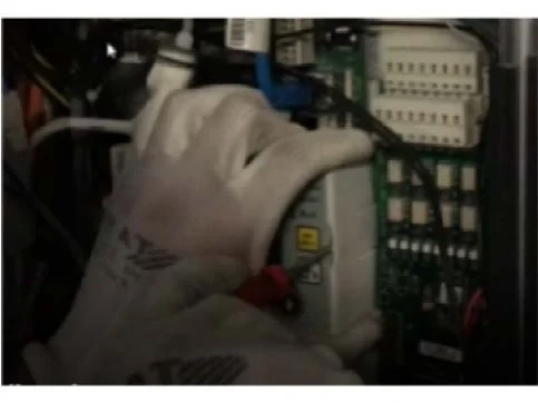
► Loosen the two lower screws that secure the SCMAIN cover to the SCMAIN circuit board.
► Remove the SCMAIN cover from the clips.
► Slide open the retaining clip of the SCCORE circuit board.
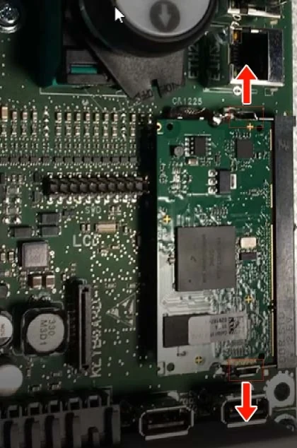
► Remove the SCCORE circuit board.
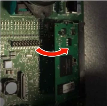
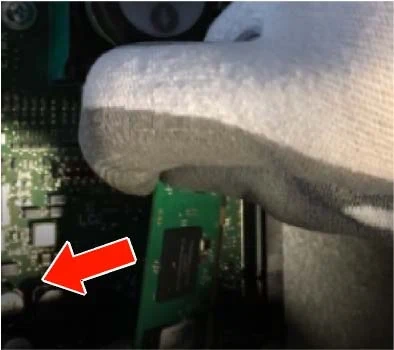
► Install the replacement SCCORE circuit board.
► Re-attach the SCMAIN cover plate, then secure it with 2 screws.
► Re-insert the SCPOW.BAT connector.
► Set switch JH to ON. The SMLCD will display a message indicating that a software download is required.
► Download the software (see the "Software Download" task).
► Record the circuit board replacement in the elevator log.
6. Replace the battery at the end of its lifespan (control cabinet).
► Check the elevator log and review the date the control cabinet battery was replaced.
► If it is > 60 months, organize the replacement materials; please refer to the spare parts list.
► Inspect the control cabinet.
► Take the elevator out of normal service; please refer to the "Preparation Tasks at the Maintenance Site" section.
► Set switch JH to OFF.
Warn
Short circuit
Risk of fire and damage to the circuit board.
Always disconnect the SCPOW.BAT plug before disconnecting the battery terminals.
► Unplug the SCPOW.BAT cable.
► Disconnect the wires from the battery terminals.
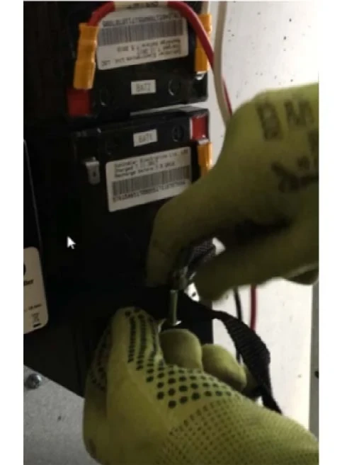
► Isolate the battery terminals.
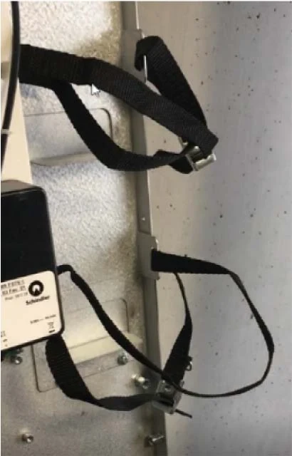
► Loosen the battery retaining strap.
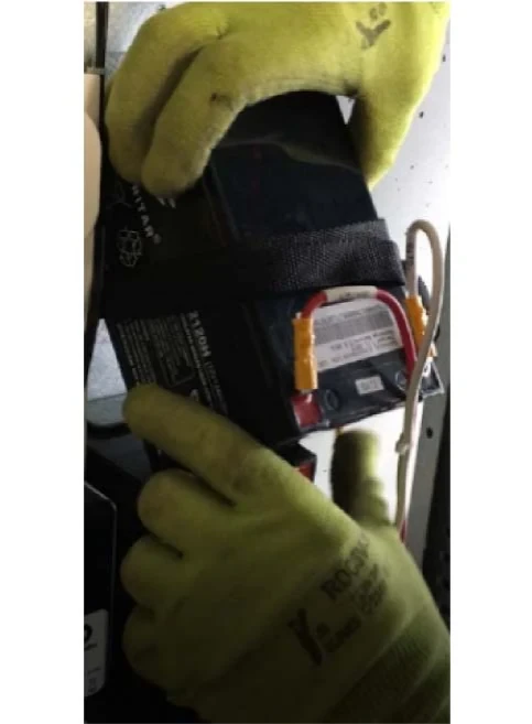
► Remove the battery.
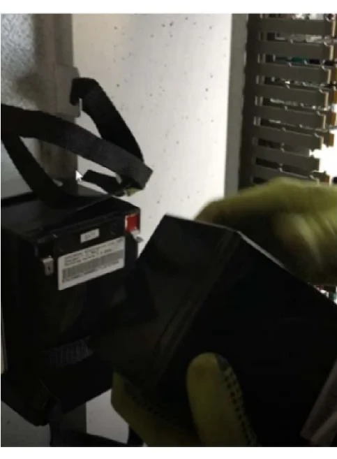
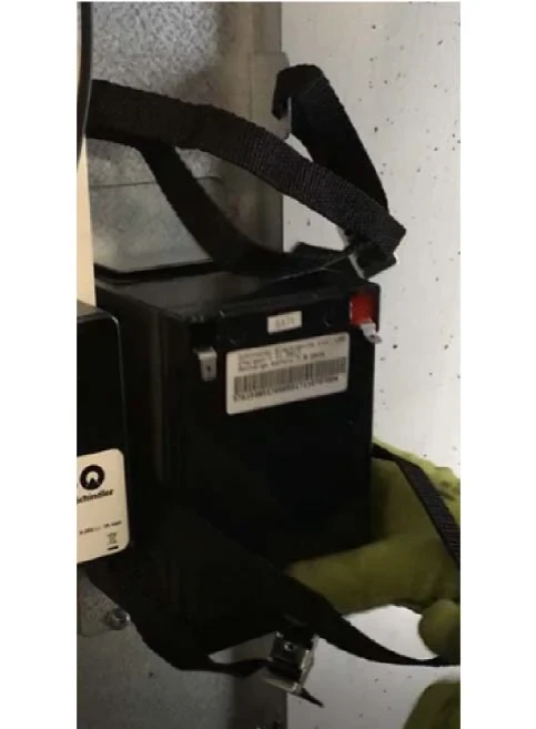
► Install the new battery.
► Tighten the battery retaining strap.
► Reconnect the wires to the battery terminals.
► Measure the voltage at the terminals of the SCPOW.BAT connector to verify the correct polarity. Refer to the installation diagram.
► Plug in the SCPOW.BAT connector.
► Set switch JH to ON.
7. Replace the battery at the end of its lifespan (AESD).
► Check the elevator log and find the date when the control cabinet battery was replaced.
► If it is > 60 months, organize the replacement materials; please refer to the spare parts list.
► When the materials are ready, take the elevator out of normal service; please refer to the "Preparation Tasks at the Maintenance Site" section.
► Access the AESD battery box.
Note:
For machine-roomless elevators, the elevator should be run to the top floor under car top inspection conditions, and this task requires two people to complete.
► Set switch JH to OFF.
► In the AESD, set switches FU1 and FU2 to OFF.
► Disconnect the wires from the battery terminals.
► Isolate the battery terminals.
► Remove the battery holder.
► Remove the battery.
► Install the new battery.
► Reinstall the battery holder.
► Reconnect the wires to the battery terminals.
► Set switches FU1 and FU2 to ON.
► Set switch JH to ON.
► Leave the car top (if it's a machine-roomless elevator).
8. i-Speci Connection
Prerequisites:
– USB to RS 232 port
– Redpark cable.
► Connect the USB to RS 232 cable to USB2 on the SC main board.
► Connect the Redpark cable to the RS 232 end (of the USB to RS 232 cable).
► Connect the other end of the Redpark cable to the Fieldlink device (iPhone).
► Open the iSpeci App and select "Connect via cable".
9. i-Speci disconnected
► Log out through the hamburger menu in the iSpeci app.
► Disconnect the USB to RS232 cable.
10. CADI Connection
► Connect the USB to RS232 adapter cable to USB2 (see item number 1 in the SCMAIN layout diagram).
► Connect the CADI cable to the RS232 side of the adapter cable.


