
1. Door Motor V15/V35
1.1. DO V15/V35, without linked landing doors.
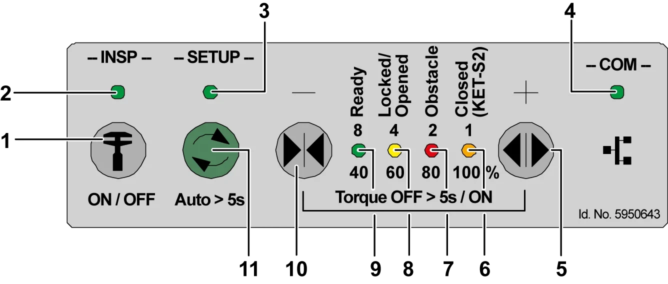
1 INSP button (Inspection) 2 INSP LED
3 SETUP LED 4 COM LED (CAN communication)
5 DRET-O button 6 locked/unlocked LED
7 Obstacle LED 8 INPS button (for Inspection)
9 Ready LED 10 DRET-S button
11 SETUP button (Settings/Automatic setup)
► CAr door: Clean all mechanical obstructions that affect door operation.
► OKR.SCCAR: Insert the following connector:
| Plug | explanation |
| DOOR | DC power supply and CAN bus - Front side DO |
| DOOR2 | DC power supply and CAN bus - Rear side DO |
| POWT | Door power supply (front and rear DO) |
| KTC | Car door contact - front side DO |
| 2KTC | Car door contact - rear side DO |
POWT: For dual-door systems, the POWT plug for each door operator is powered via an adapter T-cable through the OKR. It is then plugged into the SCCAR.POWT.
► DO V15/V35.X4-RPHT: Ensure the light curtain is connected.
If the DO Drive software is not the latest version and the light curtain is not yet installed, you may need to bypass pins 1-3 in the X4-RPHT bypass plug.
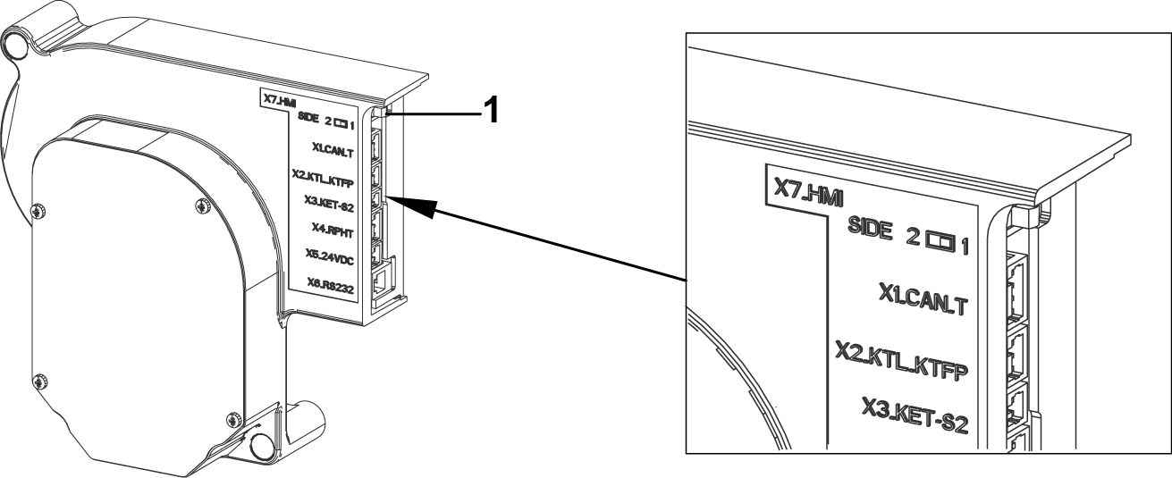
1 DO V35: Door switch in position (Side 1)
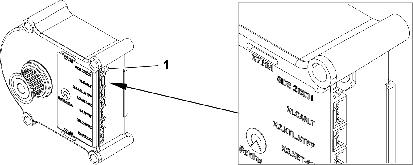
1 DO V15: Door switch in position (Side 1)
► On each DO V15/V35: Use the switch on the door operator near plug X1-CAN-T to adjust the
entrance side.
– Side 1: Flip the switch towards the car direction.
– Side 2: Flip the switch towards the landing door direction.
► AS: Set the following switches to ON:
| JH | SIS | SIL |
► AS.HMI: Waiting for the startup sequence to complete, and the HMI displays:
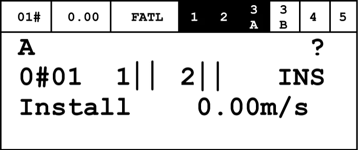
► HMI: If "Install" is not displayed, restore the status as follows:
HMI: Commands → Special Trips → MOF → ON → OK.
► DO V15/V35.HMI: Set the following switches to ON:
– JHT
– JHCT (if installed).
► DO V15/V35.HMI: Press the INSP key to start checking the door operator.
The INSP LED lights up.
► DO V15/V35: Monitor the status of the LEDs:
| LED | State | Explanation |
| INSP | ON | INSP button |
| SET | OFF | Settings not activated |
| Ready | ON | Ready |
| Lock/Unlock | Slow flashing | Reference model |
| ON | The door is locked/unlocked. | |
| Obstacle | OFF | No obstacles detected. |
| Close (KET-S2) | ON | The door panel is closed. |
| COM | ON No flash | Communication is normal |
► DO V15/V35: Check the door's direction of movement:
– Press the DRT-S (-) button to immediately monitor the closing direction.
– Press the DRT-O (+) button to immediately monitor the opening direction.
– If the direction of movement is correct, proceed to the "Commissioning the V15/V35 Door Operator for Interlocked Landing Doors" section.
– If the direction of movement is incorrect, proceed with the following steps:
► DO V15/V35: Set the power switch to OFF.
– JHT
– JHCT (if installed)
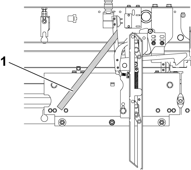
1 KTC contact arm
► If a car door lock is installed, use tape/cable ties to insert the KTC contact arm into the door bracket. This keeps the lock hook in the unlocked position.
► The car door can open and close automatically.
► DO V15/35: Manually close the car door.
► DO V15/V35: Set the power switch to ON.
– JHT
– JHCT if installed.
► DO V15/V35 HMI: Press the INSP key to start the door operator inspection.
The INSP LED lights up.
► DO V15/V35: Press the Setup/AutoSetup button for more than five seconds to start automatic setup.
– SETUP LED flashes slowly = AutoSetup is in progress.
– The car door opens a short distance.
– The car door locks.
– The door opens and closes 3 to 5 times to evaluate door parameters.
– The car door closes.
– SETUP LED turns off = Automatic setup is complete.
► DO V15/V35: If the automatic setup is not satisfactory:
– SETUP LED, Closed (KET-S2) LED, Obstacle LED,
Locked/Opened LED, and Ready LED flash rapidly.
– Press the "Setup" button to clear the error, then perform "Automatic Setup" again.
– Ensure that the mechanical car door adjustment conforms to the EMBD document.
– Please refer to the diagnostic documents:
– V15-EJ 41354325
– V35-EJ 41350884.
► If a car door lock is installed, remove the tape/cable ties used to block the KTC contact arm.
1.2. Heavy-Duty Door DO V35
► The following conditions must be ensured:
– The landing door and car door panels are made of glass or have larger dimensions, with a moving mass of 240...400 kg.
– All landing doors are of the same type.
– All landing doors have the same weight.
– All landing doors have a closing counterweight (no closing spring).
► AS.HMI: Set the value of the VD35 parameter.
HMI: Parameters → VD35 Param
→ VD35 Param ID = 25 → VD35 Param = 1 → OK.
► Repeat this step for side 1 and side 2.
1.3. DO V35 for landing doors with different counterweights
► Ensure the following conditions are met:
– There are two different types of landing doors with different weights.
– The moving mass of the doors at each landing is less than 240 kg (car door and landing door).
► AS.HMI: Set the value of DO V35 parameter number 25:
– Side 1 (front side) to 0:
o HMI: Parameters → VD35 Param → VD35 Param ID = 25 → VD35 Param = 0 → OK
– Side 2 (rear side) to 0:
o HMI: Parameters → 2.VD35 Param → VD35 Param ID = 25 → VD35 Param = 0 → OK.
The landing door arrangement must be consistent with the civil engineering drawings.
► For Side 1 (front side), define the standard weight landing door ("Normal Door") and the heavy-duty landing door ("Heavy Door") in the "Floor Door Mapping Table".
– AS.HMI: Parameters → Door → LanDoorWeight
– Side 1 → Floor = 1 → OK → 'Normal Door' or 'Heavy Door' → OK
– Side 1 → Floor = # → OK → 'Normal Door' or 'Heavy Door' → OK
– Perform this step for each landing.
► For side 2 (rear side), define standard weight landing doors ("Normal Door") and heavy-duty landing doors ("Heavy Door") in the "Floor Mapping Table".
– AS.HMI: Parameters → Door → LanDoorWeight (Landing Door Weight)
– Side 2 → Floor = 1 → OK → 'Normal Door' or 'Heavy Door' → OK
– Side 2 → Floor = # → OK → 'Normal Door' or 'Heavy Door' → OK
– Perform this step for each floor landing.
1.4. DO V15/V35, with connected landing doors
- During automatic setup, all safety devices are operational, such as KSKB and KOKB, except for RPHT. The automatic setup program stops if any safety device is activated.
- Before starting this process, complete the specific adjustments for the heavy-duty landing doors used on sides 1 and 2.
- For sides 1 and 2, complete the following settings for the landing doors at the following floors:
o Standard landing doors
o Heavy-duty landing doors.
► DO V15/V35: Lock the car door.
If the car door is unlocked, press the DRET-S button until the "Lock/Open" LED indicator lights up.
► Manually close the landing door.
► DO V15/V35 HMI: To exit inspection mode, press the INSP button.
– The INSP LED turns off.
► OKR.REC: Press the DREC-U or DREC-D button to move the car to the door zone. When the car is in the door zone, the blue LUET LED on the AC GSI main sensor lights up.
► DO V15/V35 HMI: To start door inspection, press the INSP button.
– The INSP LED lights up.
► DO V15/V35: Press the Setup/AutoSetup button for more than five seconds to start automatic setup.
– When the SETUP LED flashes slowly, it indicates that AutoSetup is in progress.
– The car door opens a short distance.
– The car door locks.
– The door opens and closes 3 to 5 times to evaluate door parameters.
– The car door closes.
– SETUP LED off = Automatic setup complete
► DO V15/V35: If automatic setup fails:
– The SETUP LED, Closed (KET-S2) LED, Obstacle LED, Locked/Opened LED, and Ready LED will flash rapidly.
– Press the "Setup" button to clear the error, then start "AutoSetup".
– Ensure the mechanical car door adjustment conforms to the EMBD file.
– Refer to the diagnostic document DO V15/V35.
► DO V15/V35: Check door movement and performance.
Control door movement by pressing the DRET-O or DRET-S buttons.
– Perform two to three complete opening and closing cycles.
– Monitor the door stopping at full opening speed. Stop the door midway.
– Monitor the door stopping at full closing speed. Stop the door midway.
► DO V15/V35: Set the door open position.
– Press the DRET-O button to fully open the car door.
– Press the SETUP button. The SETUP LED lights up.
– Press the DRET-S or DRET-O button to align the door with the door frame. The door moves in 1 mm increments.
– Press the SETUP button to save the aligned position.
The saving process stops 30 seconds after the SETUP LED lights up. The SETUP LED turns off.
If this step is not completed on the HMI, the aligned position will not be saved.
► DO V15/V35: Ensure the car door and landing door are properly aligned. Also monitor the movement of the door knife.
– Press the DRET-S button until the "Locked/Opened" LED lights up.
– Press the DRET-O button for no more than 0.2 seconds to open the door knife.
– Perform the locking/unlocking procedure 2 or 3 times to ensure the car door panel and landing door panel do not move.
If no movement is observed, the car door and landing door are properly aligned.
► DO V15/V35: Set the opening and closing speeds. – Press the DRET-S button until the "Lock/Unlock" LED indicator lights up.
– Press the SETUP button.
– Select a speed value from 100%, 80%, 60%, and 40%.
– Repeatedly press the DRET-S or DRET-O button to change the speed value.
– Press the SETUP button to store the selected speed value.
If the selected speed value is not stored within 30 seconds, the storage procedure ends. The SETUP LED turns off.
If this step is not completed on the HMI, the position will not be stored.
► DO V15/V35 HMI: To exit maintenance mode, press the INSP button. The INSP LED turns off.
1.5. Final Inspection of Door Operator V15/V35
► OKR.REC Panel: Set the following switches to the following positions:
– JREC to INSPECTION
– JHC to RELEASED.
► Ensure the car door is closed and locked and the car moves:
– Press DREC-D and DREC-E simultaneously:
The car moves downwards.
– Press DREC-U and DREC-E simultaneously:
The car moves upwards.
2. Debugging SCANIBV for parallel gate machines
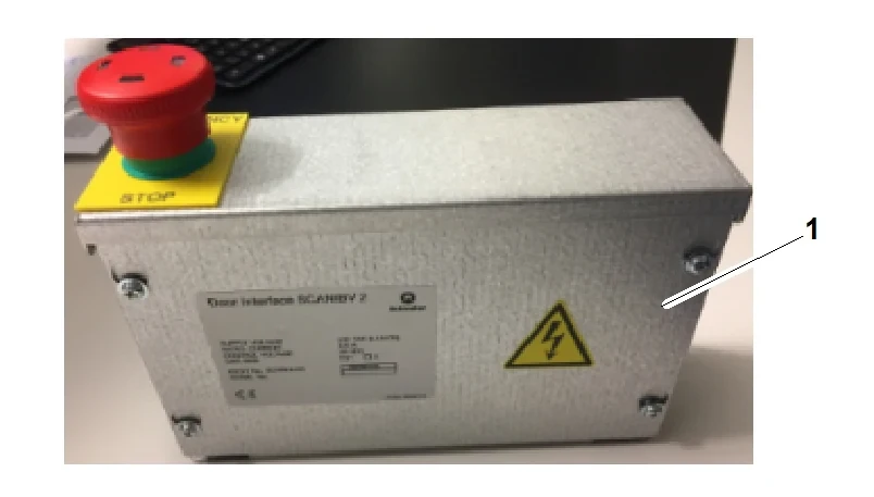
1 Car door interface box with JHCT stop switch SCANIBV
► DOOR Interface.SCANIBV: The input of the SCANIBV PCB inside the car door interface box.
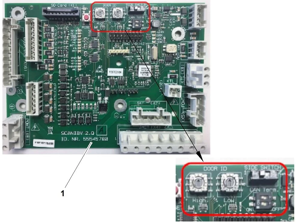
1 Top view of the SCANIBV PCB
► DOOR Interface.SCANIBV: Ensure that the elevator door ID, entrance side switch, and control type settings are consistent with the current elevator system.
| Adjustment type | Parameter | Parameter value | Set |
| Car door ID | CDO (Car Door Operator) | DO SEC | High 0 Low 5 |
| DO WIF | High 0 Low 8 | ||
| DO SEB | High 0 Low 5 | ||
| Inlet side switch | SZ | 1 | 1 |
| 2 | 2 | ||
| CAN terminal | Control type | CO MX 7.2 | Switch 1: ON Switch 2: ON |
| CO SC 1 | Switch 1: Off Switch 2: Off |
► OKR.SCCAR: Insert the wiring connector from the OKR.SCCAR PCB to the DOOR.SCANIBV PCB.
| OKR.SCCAR Plug | Explanation | DOOR.SCANIBV Plug |
| DOOR | DC power supply and CAN bus | X3 |
| KTC | Car door contact point | X7 |
| POWT | Power supply POWT | X5 |
POWT: For dual-entry systems, the POWT plugs (POWT and 2POWT) for each door operator are powered via an adapter T-cable through the OKR. These are then plugged into OKR.SCCAR.POWT.
► DOOR Interface.SCANIBV: Ensure the following door contacts are connected:
| DOOR.SCANIBV plug | door contact |
| X4 | JHCT |
| X8 | KTC, KTC2 |
| X9 | Light Curtain |
If the light curtain is not connected: bypass pins 1 and 3 in the bypass plug X9.


