1. Control cabinet
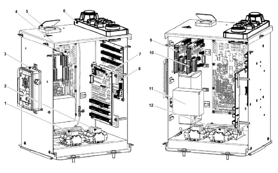
The control cabinet comes in three models optimized for different elevator system layouts.
1.1. Machine room-less control cabinet
The machine-roomless control cabinet is installed next to the door frame. It includes the machine-roomless control cabinet frame and the back panel.
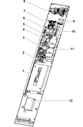
1 Switch Module
2 SCAES Printed Circuit BoArd (Optional)
3 Intercom/Remote Alarm Device
4 JRH/JEM Switch
5 SCPOWL11/H11/H12 Printed Circuit Board
6 HMI (Display + Keyboard)
7 SCMAIN 11/12/13/14 + SCCORE 11/12 Printed Circuit Board
8 Terminals and Options (RBFF1, ETH Switch)
9 IFSCVF Printed Circuit Board (Optional)
10 LDBCS Panel (Optional)
11 Battery Pack
12 Power Supply (NGL+NGO)
1.2. Small equipment room control cabinet
The small server room control cabinet is a self-contained unit and can be mounted on the server room wall or floor using the included floor mounting kit.
Tip:
For elevators affected by seismic conditions (EN81-77 and other standards), control cabinets installed on the floor of a small machine room are not suitable (as shown in the image below).
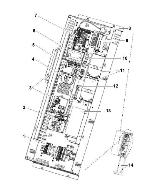
1 Terminal
2 SCAES PCB (optional)
3 Intercom/Remote Alarm Device
4 JRH/JEM Switch
5 SCPOWL11/H11/H12/H13 PCB
6 HMI (Display + Keyboard)
7 SCMAIN 11/12/13/14 + SCCORE 11/12 PCB
8 Stop Button
9 Optional (RBFF1, ETH Switch)
10 LDBCS Panel (optional)
11 Battery Pack
12 IFSCVF PCB (optional)
13 Power Supply (NGL + NGO)
14 Floor Mounting Kit (optional)
1.3. LDU Module
The LDU control cabinet is integrated into the door frame or placed near the door, and consists of two modules, a base, and a power supply. The image below shows the LDU enclosure and the built-in control modules.
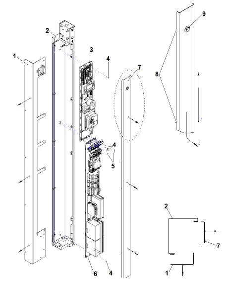
1 LDU - Installation Cover
2 LDU - Fixing Part
3 Base Module
4 Module Fixing Nut
5 Module Grounding Nut
6 Power Supply Module
7 LDU - Maintenance Cover
8 LDU – Maintenance Cover Hook
9 LDU - Triangular Lock
1.4. Basic Modules
The basic module is a self-contained component that can be installed in the lobby door unit. There are two types:
1. With integrated automatic evacuation function
2. Without integrated automatic evacuation function
The image below shows the basic module assembly type with integrated automatic evacuation.
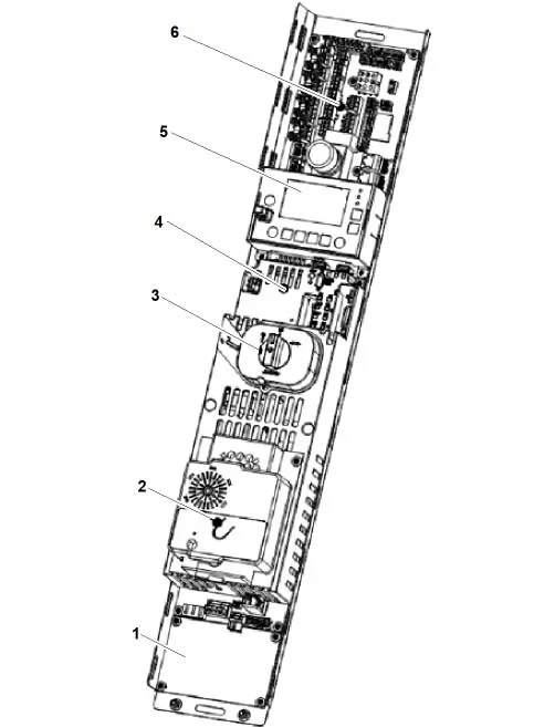
1 SCAES circuit board (optional)
2 Intercom/remote alarm device
3 JRH/JEM switch
4 SCPOWL11/H11/H12 circuit board
5 HMI (display + keyboard)
6 SCMAIN 11/12/13/14 + SCCORE 11/12 board
1.5. Power supply module
The power supply module is a separate component that can be installed in the door unit. There are two types:
1. LDU for left-side mounting
2. LDU for right-side mounting
The image below shows the power supply module assembly for the left-side version.
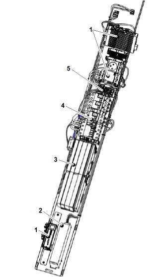
1 Optional components (SHE, ETH switches)
2 Power supply (NGL)
3 Battery pack
4 Switch module
5 Terminal
2. Elevator car control panel
– Standard OKR, vertical orientation, with fixed REC
– Standard OKR, vertical orientation, with movable REC
– Extended OKR, with fixed REC panel
– Extended OKR, with movable REC panel
Tip:
OKRs with a fixed REC panel come in two types:
1. REC is on the left side or
2. REC is on the right side
The OKR can be selected based on its position on the car top to maintain a safe distance of 300 mm (placement mark equal to or less than) between the REC and the car top (EN81-20 clause 5.4.8.a).
2.1. Standard OKR, vertical orientation, with fixed REC panel.
If the local standard is EN81-20/50, then this type of OKR should be selected, and the following optional features are not required:
– Elevator car card reader interface
– Third-party peripherals
– CANGIO circuit board
– NGC power supply
The available models are as follows:
– REC is on the right side
– REC is on the left side
The decision to use the REC on the right or left side depends on the vehicle's roof layout and the OKR position.
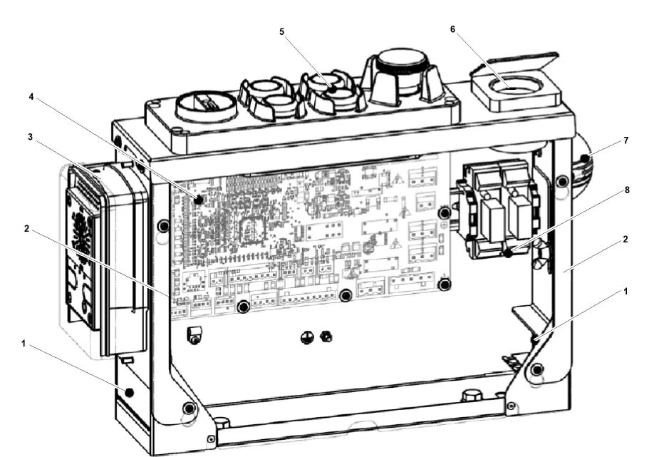
The image above shows the REC unit on the left, in the OKR configuration, without a maintenance cover.
1 Wiring opening
2 Gasket seal (IPX3)
3 Tri-phonie option (with IPX3 cover)
4 SCCAR 11/12/13/14 printed circuit board
5 REC panel
6 Car top power socket
7 SOA speaker (optional)
8 Weekend operation or dual-speed fan optional
2.2. Standard OKR, vertical orientation, with active REC panel
If the local standard is EN81-20/50, then this type of OKR should be selected, and the following optional features are not required:
– Elevator car card reader interface
– Firefighter elevator based on EN81-72
– Third-party peripherals
– CANGIO circuit board
– NGC power supply
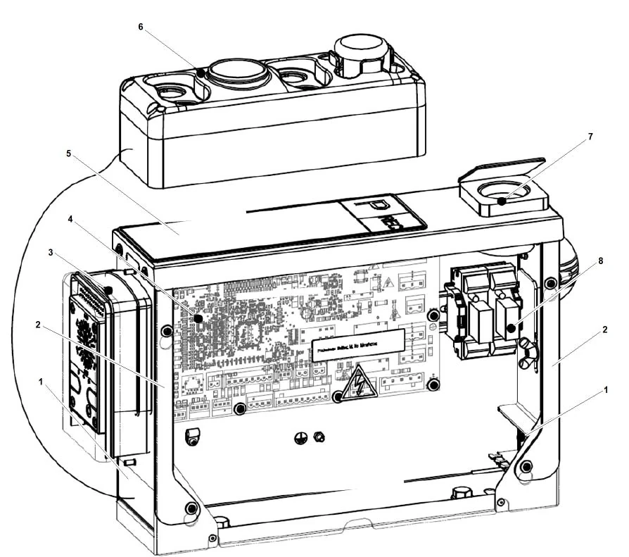
1 Wiring opening
2 Gasket seal (IPX3)
3 Tri-phonie option (with IPX3 cover)
4 SCCAR 11/12/13/14 printed circuit board
5 REC panel docking sticker and magnet
6 REC panel
7 Car top power socket
8 Weekend operation or dual-speed fan optional
2.3. Extended OKR with fixed REC panel
If the local standard is EN81-20/50, then this type of OKR should be selected, and at least one of the following options is required:
– Elevator car card reader interface
– Third-party peripherals
– CANGIO circuit board
– NGC power supply
The available models are as follows:
– REC is on the right side
– REC is on the left side
1 Optional operation on rest days
2 Optional two-speed exhaust fan
3 Tri-phonie option (with IPX3 cover)
4 SCCAR circuit board 11/12/13/14
5 Car top power socket
6 REC panel
7 Second CANCPI optional
8 First CANCPI optional
9 First CANGIO optional
10 Second CANGIO optional
11 NGC power supply
12 RNGC relay
2.4. Extended OKR with active REC panel
This OKR is applicable only if the following conditions are met: it is installed on elevator car CA PK33, the local standard is not EN81-20/50, the elevator is located in Singapore, Australia, or Malaysia, and none of the following options are required:
– Elevator car card reader interface
– Firefighter elevator based on EN81-72
– Third-party peripherals
– CANGIO circuit board
– NGC power supply
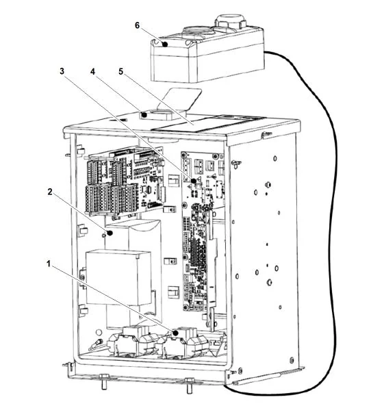
1 Relay RMVEC1-A (optional)
2 Car fan UPS (optional)
3 SCCAR circuit board 11/12/13/14
4 Car top power socket
5 REC panel docking sticker and magnet
6 REC panel
3. HMI
3.1. Overview
The HMI (Human-Machine Interface) is the user interface for the CO SC controller. It is used for debugging, parameter adjustment, testing, and diagnostics.
It includes:
– Display (SMLCD)
– Keyboard
– Plastic case
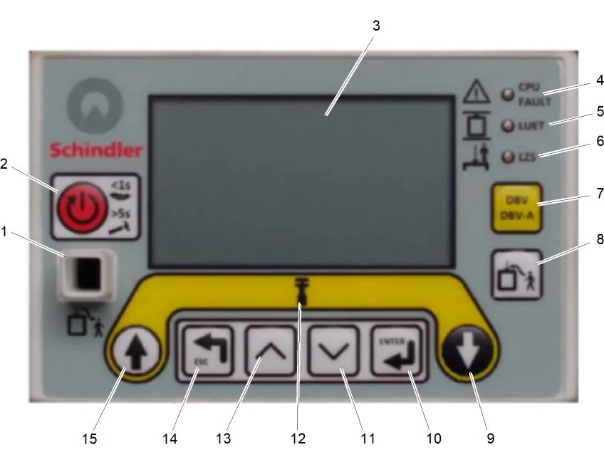
1 TSD21 Reset Button (lockable), for SPH elevators
2 Reset Button
3 SMLCD
4 Elevator Fault
5 LUET (Door Zone)
6 LZS: KNET Feedback
7 Overspeed Test
DVB = Trigger
DNB-A = Reset
8 Car Automatic Positioning - Car Top Maintenance
9 Down Maintenance Button
10 Enter Button
11 Scroll Down Button
12 Maintenance Mode
13 Scroll Up Button
14 Exit Menu Button
15 Up Maintenance Button
Tip:
Press the reset button for less than 1 second for a software reset.
Press the reset button for more than 5 seconds for a hardware reset.
A hardware reset clears temporary software flags.
Items 10, 11, 13, and 14 are referred to as SMLCD navigation buttons.
3.2. Keyboard Shortcuts
The following special key sequences can be used as shortcuts to quickly access specific menu items (these are not context-sensitive and are always available).
| Key sequence | operate |
| ESC + UP | Pressing both buttons simultaneously provides direct access to the Status Lift (elevator status) display. |
| ESC | Using the keyboard shortcut ESC + UP, you can return from the Status Lift (elevator status) screen to the location where you previously accessed the elevator status. |
| ESC + OK | Pressing both buttons simultaneously will directly access the in-car elevator call function (the original position in the menu tree will be restored after the elevator call is completed). |
| ESC + 2x UP | Press and hold the ESC button, then press the UP button twice to initiate an explicit logout. |
| ESC + DOWN | Pressing both buttons simultaneously allows you to return directly to the current submenu from a lower-level activity. |
| UP + DOWN | Change the editing mode to enter values (parameters): Editing Mode 1: Scroll through the entire range. Editing Mode 2: Scroll through individual digits. |
4. SMLCD
SMLCD is the display screen for the HMI (Human-Machine Interface) and serves as the user interface for the CO SC controller.
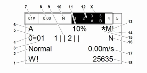
X Status bar
1 Traction steel belt
2 Operation Control
3 Current group selector value
4 Drive status
5 Car status
6 Elevator number within the group
7 Car status
8 Running speed
9 Door
10 Activate control service
11 LMS
12 Safety circuit status
13 Node tree
14 Main elevator
15 Service access
16 Activate control service
17 Running speed
18 Calculated values during normal operation/power failure/startup process
| Status line (X) | |
| When navigating through menu X (7, 8, 10, 12), the status bar is always present. | |
| Traction steel belt (1) | |
| W! Flashing | The traction steel belt monitoring has reached the warning limit. |
| E! Flashing | The traction steel belt monitoring system has reached its locking limit. |
| C! Flashing | The date and time settings (RTC) for monitoring and detecting faults in the traction steel belt. |
| Operation Control (2) | |
| When a malfunction occurs: | Displays the ability to switch between fault codes and status. |
| IniPara | The controller is initializing the motor control parameters. |
| Precomm | The controller requires a learning run. |
| Install | The controller is in the installed and running state. |
| Learn | The controller is currently performing a learning run. |
| Synch | The controller is performing a synchronous operation. |
| Insp | The controller is in inspection mode. |
| Recall | The controller is in recall operating mode. |
| Relevel | The controller is performing a re-leveling operation. |
| BlkTemp | Due to a malfunction, the controller has been temporarily locked. |
| BlKPerm | Due to a critical failure, the controller has been permanently locked. |
| Controller | The controller is performing an operation triggered by DFM-D/U. |
| T1Open | The safety circuit is disconnected at T1. |
| T2Open | The safety circuit is disconnected at T2. |
| T3AOpen | The safety circuit is disconnected at T3A. |
| T3BOpen | The safety circuit is disconnected at T3B. |
| T4Open | The safety circuit is disconnected at T4. |
| JHM On | The controller was stopped by JHM. |
| JHC On | The controller was stopped by JHC. |
| JHC1 On | The controller was stopped by JHC1. |
| SwtchCon | Switch consistency. The controller detects an inconsistency between the two inputs reading the JRH switch (N_JRH and JRHCHK) states (both are 0 or 1). This prevents the elevator from operating in normal mode. |
| FC_NRdy | The variable frequency control system is not ready for operation. |
| DoorByp | Hall door bypass activation |
| BypNMan | The bypass switch (JUEKTS) next to the control panel door is ON, but neither of the inspection switches (JRH or JREC) is switched on. The system cannot operate normally. |
| KTHMH | Traction motor overheating |
| VFOvTmp | The frequency converter is overheating. |
| Lift24V | 24 VDC power supply is missing. |
| SB Fault | The controller stopped due to a fault in the brake contactor. |
| LMSnRdy | Weighing system not ready. |
| Correct | The elevator is undergoing calibration. |
| PEBOFlt | The PEBO device has malfunctioned. |
| Creep | The controller terminates operation via the speed encoder. |
| BatFlt | The emergency power supply battery has malfunctioned. |
| Ovrload | Elevator overload |
| AccTBlk | After the acceptance testing, the elevator was locked. |
| RdyBVR | The speed limiter reset is ready. The controller has detected the condition that occurred when the GBP_RESET plug was inserted (safety circuit closed, but the logic state of the KBV input was disconnected), and will only allow maintenance and recall operations up to the speed limiter, which must then be manually reset. |
| BMIni | Brake emergency stop monitoring awaiting initialization. |
| BMErr | The brake emergency stop monitoring has been triggered. |
| PEBOBat | The battery of the manual evacuation device is depleted. |
| Current group selector value: 1 ... n (3) | |
| Drive status (4) | |
| 0 | The drive is in a stationary state. |
| + | The drive is accelerating. |
| = | The drive operates at a constant speed. |
| - | The drive is slowing down. |
| F | Driver unavailable |
| ? | Unknown drive state |
| Elevator car status (5) | |
| = | The elevator car is stationary within the door zone. |
| # | The elevator car is stationary outside the door area. |
| ↑ | The elevator car is moving upwards. |
| ↓ | The elevator car is moving downwards. |
| ? | Unknown elevator car status |
| Elevator number within the group (6) | |
| Compartment status (7), same information as position 5. | |
| Operating speed (8) | |
| Door (9) | |
| 1/2 | door side |
|
| The door opened. |
|
| The door is closing. |
|
| The door is opening. |
|
| The door is closed. |
|
| The door is locked. |
|
| The gate is stopped or unavailable. |
|
| Status unknown |
| Activation control service (10), same as location 16. | |
| LMS (11) | |
| CAL | The LMS needs calibration. |
| CALF | The LMS requires zero-load calibration related to the floor level. |
| UNV | LMS is unavailable. |
| DIS | LMS is disabled. |
| xx% | Ratio of car load to rated load (%) |
| Safety circuit status (12), the black background indicates that the safety circuit remains closed up to this point. | |
| Node Tree (13) | |
| "%" Flashing | Downloading node software... |
| "?" | Requesting the node tree to be frozen. |
| "?" | Execute node tree freezing. |
| "!" | Freezing failed. |
| "!" | After freezing, some nodes are missing or new nodes are detected. |
| Blank | The freeze has ended, and the node tree remains unchanged. |
| Main elevator (14), ("M" = This elevator is the main elevator in the group; a blank space indicates it is not the main elevator) | |
| Service access (15), (* flashes when service access is active, blank when inactive) | |
| Activation Control Service (16) | |
| Operating speed (17) | |
| When a malfunction occurs: | Displays the ability to switch between motor control status and fault codes. |
| Calculated values during normal operation/power failure/startup process (18) | |
| Operating normally | Different modes can be used: IMOF (Installation and Operation Information) Traction steel belt running counter value (calculating the bending of the STM) |
| Power failure | The distance between the elevator car and the nearest floor in case of a power failure. "+" indicates that the elevator car is above the floor. |
| During the startup process | Instructions regarding the I/O scanning process. |