
1. Turn on the LCD device
Step ① Connect the main LCD controller and the auxiliAry LCD controller to the power supply, the controller starts, and the main and auxiliary LCD display devices light up (white screen). After a few seconds, the screen displays the startup interface, as shown in Figure 1-1. Wait for the operating system to start, and after about 40 seconds, the screen displays as shown in Figure 1-2.
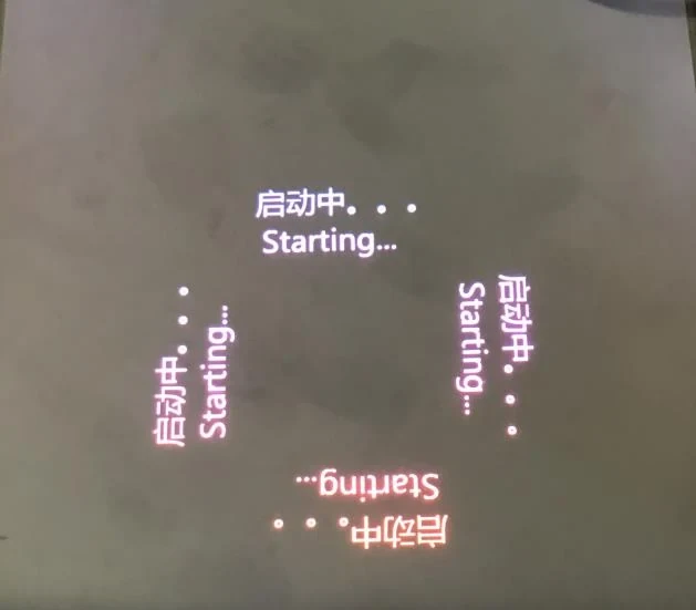
Figure 1-1 Startup screen

Figure 1-2 Application display screen
After the screen in Figure 1-2 appears, you can start debugging and setting.
If the screen displays horizontal stripes, you need to check whether the LVDS cable connection is in good contact. If necessary, please replace the LVDS cable for testing.
2. LCD controller setting server IP
Method 1: On-site PC debugging (debugging personnel configure laptops, no need to install host computer software)
① Change the local IP of the computer to 192.168.80.X (X can be 2-255, please do not set it to 192.168.80.1)
As shown below:
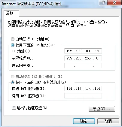
Figure 2-1 Modify the local IP address
② Open the browser and enter http://192.168.80.1:8080/config/, username: smec30, password: 200236. Click Login, as shown below:
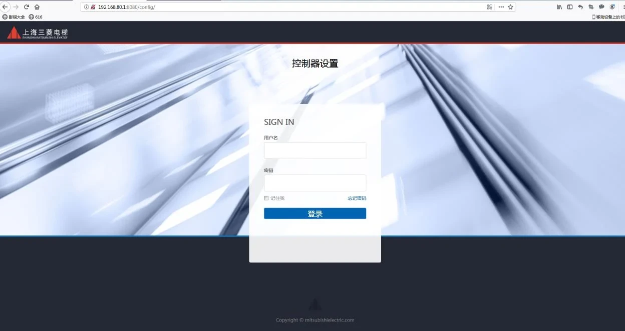
Figure 2-2 Login
③ Modify the IP address in the page (modify the settings according to the network segment required on site), server IP (the local IP address of the computer where the host computer is installed), and click Save. No need to plug and unplug the network cable, refresh the page several times, and wait for the host computer to display the connection.
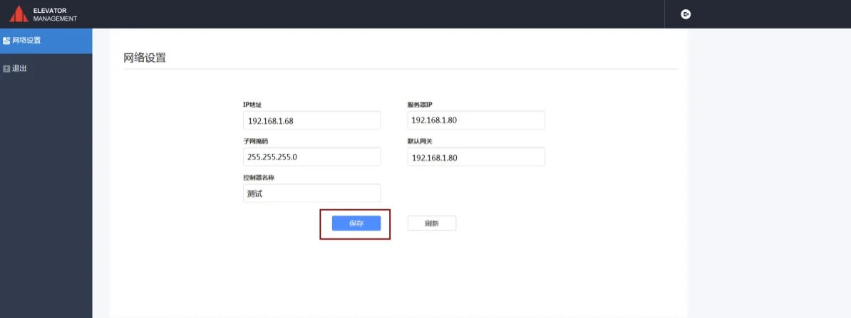
Figure 2-3 Modify IP address
④ After completing the above steps, open the host computer page and check the connection status. If it is green, it means the modification is successful and the controller has been successfully connected to the host computer.
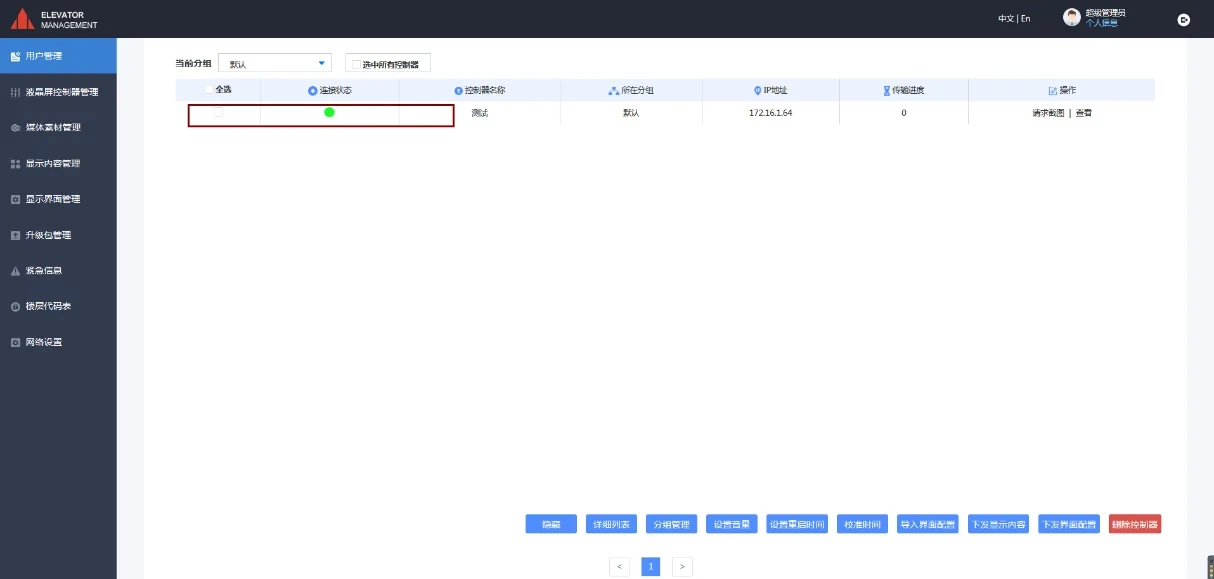
Figure 2-4 Checking the connection status
Step ⑤ Check the network. Move the PC to the machine room (next to the control cabinet if there is no machine room), connect it to the Ethernet converter first, and ping the controller (ie ping 192.168.80.1). If it is normal, it means that the network connection from the machine room to the car top is normal, otherwise you need to check the Ethernet converter.
Method 2: On-site mouse modification (i.e. the debugging personnel configure the mouse and set it on the LCD screen interface)
① Connect the power supply to start the controller normally and enter the main interface. After opening the component on site, use the mouse to connect to the USB interface (CN30) of the control board, slide the mouse and click the upper left corner of the interface, as shown below

Figure 2-3 Open IP window
② Connect the network cable to the network interface (CN42). When there is a DHCP server in the network, click on the "Auto-acquire" option in the IP address area, as shown below:
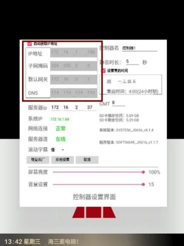
Figure 2-4 Automatically obtain IP
③ If there is no DHCP server in the network, you can modify it manually (network segment, subnet mask, modify the settings according to the site requirements)
As shown below:
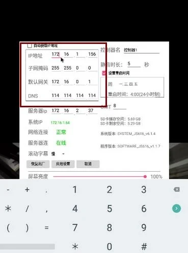
Figure 2-5 Manually modify IP
④ Modify the server IP, check the local IP address of the computer where the host computer is installed (IP viewing method, Start-Run-enter cmd--ipconfig), and enter it into the server IP. After entering, click Apply Settings.
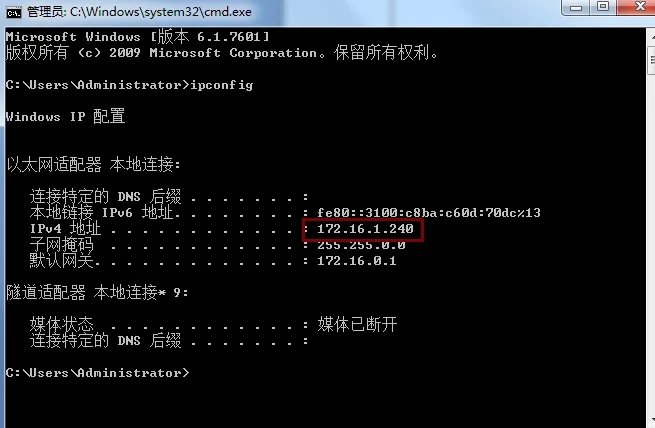
Figure 2-6 Viewing the local IP address
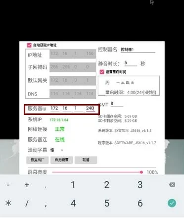
Figure 2-7 Enter the server IP
Step ⑤ Check the network. Move the PC to the machine room (next to the control cabinet if there is no machine room), connect it to the Ethernet converter first, and ping the controller (ie ping 192.168.80.1). If it is normal, it means that the network connection from the machine room to the car top is normal, otherwise you need to check the Ethernet converter.


