
1. Inverter DC circuit inspection
The DC circuit test checks the voltage and functionality of the following components: SGRW, SH, input rectifier, braking chopper, braking resistor, and capacitor bank.
► AS.ESE panel: Set the following switches to the following positions:
– JRH to NORMAL
– JHM to RELEASED.
► Ensure the safety circuit is closed.
► HMI: Perform a DC link test.
HMI: Tests → VF test → DC link test → OK

2. Motor current loop check
The current loop test checks the following: motor circuit IGBTs, wiring from the FC to the MH, inductance, and load symmetry.
► Ensure the safety circuit is closed.
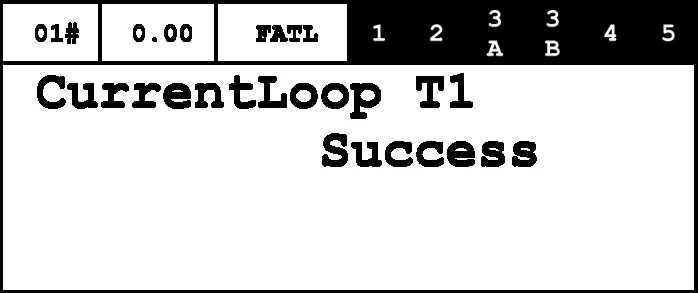
► HMI: Perform the current loop test.
HMI: Tests → VF test → Current Loop test → OK
3. PM traction motor zero position check
- The zero-position test is only applicable to PM traction machines (synchronous models).
- Asynchronous traction machine names begin with "F". This test is not required for asynchronous traction machines.
- The zero-position test can detect discrepancies between the rotor position and the motor encoder position.
► Ensure the traction medium is not yet installed.
The motor will stArt for a few seconds during the zero-position test.
► Ensure that:
– The traction machine is of the synchronous type.
– The DC circuit test is completed.
– The current loop test is completed.
► AS. SCMAIN.ESE: Disconnect the recall control panel.
 Warn
Warn
During the motor zero-position check, the elevator car suddenly moved.
When checking the zero position of the PM traction motor, the motor rotated for several seconds. Therefore, if the traction media had already been installed for any reason, the elevator car could move upwards by more than two meters, posing a real risk of collision.
If testing is required with the traction media already installed, ensure that the elevator car is positioned at a distance greater than 3 meters below the top floor or machine room floor.
The described steps must be strictly followed to ensure the correct execution of the inspection procedure.
► AS.SCMAIN.ESE: Use the IMOF package to install the recall control panel onto the recall control plugin, as shown below.
| IMOF plug - Identification number 57816206 |
| AS.SCMAIN.ESE-HK |
| HK-[ESE+TSD] |
| TSD |
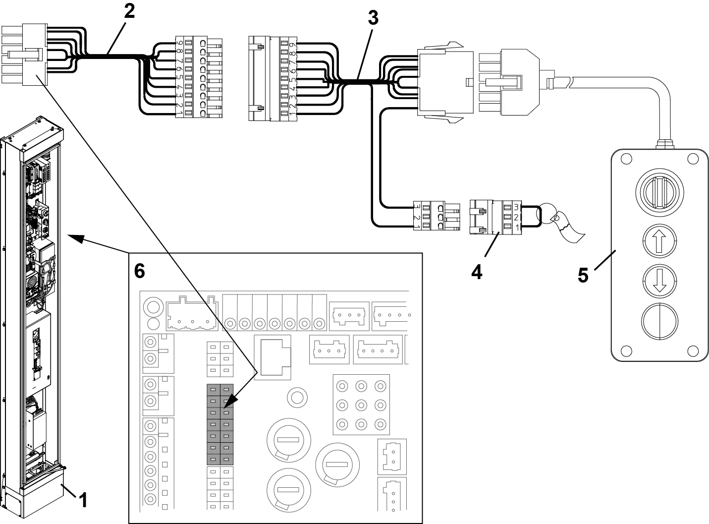
1. AS – Control Cabinet 2. AS.SCMAIN.ESE-HK – IMOF Connector
3. HK-[ESE+TSD] – IMOF Connector 4. TSD – IMOF Connector
5. ESE Panel 6. AS – SCMAIN PCBA
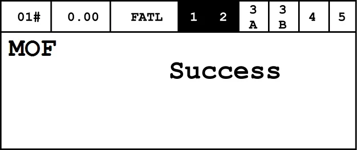
► HMI: Set the installation and operation mode to MOF.
HMI: Command → Special Trips → MOF → ON → OK.
– HMI displays "Success".
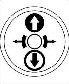
► AS.ESE panel: Set the switch position to:
– JRH to INSPECTION.
► AS.SCMAIN.DEM/DRH: Ensure the LED on the DEM/DRH-E button is illuminated.
► HMI: Perform zero position test.
HMI: Tests → VFTest (Variable Frequency Drive Test) → ZeroPositionTst t3 → OK.
► HMI: Wait until the "Begin Test" message is displayed.
► AS.ESE panel: Press and hold the DRH-D or DRH-U button until the elevator car stops.
► In case of emergency, release the DRH-D or DRH-U button.
► AS.ESE panel: Release the DRH-D or DRH-U button.
► Wait 3...5 seconds.
► Repeat the last four steps until the HMI displays:

► MR.ACVF: Monitoring the status of the LED:
| LED (color) | state | explanation |
| ERROR (red) | OFF | No fault |
| OK (green) | ON | All parameters are available. |
| PARAMETER (yellow) | OFF | Correct debugging |
► HMI: Save changes using the "End Commission Command":
HMI: Commands → Drv End Commis → OK.

Then, the drive parameters are saved to the storage device.
► HMI: If the zero position test has been performed, please ensure that the parameter value is not zero.
HMI: Parameter → ACSyn Motor → ZeroPosition ≠ 0.
If the ZeroPosition value is 0, perform the zero-position test again.
► HMI: Adjusting the control clock date and time:
HMI: Parameters → System → Date.
Parameters → System → Time.


