
Landing Station Bus
1. PrepAration of the station bus
1.1 There are two types of station bus systems:
① BIO Bus: Used in KA, KS, and PI elevators to connect the following devices:
- FIGS LIP and LOP
- Third-party peripheral interfaces LCUM and LCUX
- Maintenance panel RESG
- Building interface BIOGIO.
② CAN Bus: Used in M10 elevators to connect the following devices:
- ZL3 terminal
- Car destination floor panel (CDP)
- Building interface and CANGIO.
1.2 Clear BIO Nodes
The Clear BIO Nodes function is used to start self-learning from the original node. This function removes the configuration of
all nodes connected to the BIO bus.
HMI: Commands → Clear BIO nodes
► AS.JH: Set JH to OFF.
► On each floor: Ensure the lobby bus is connected to:
– LOP.XBIO
– LIP.XBIO
– GIO.XBIO
► Building Interface Box: Ensure that the BIOGIO PCBA (up to three units) have different CFG switch settings.
| Hardware Name | Software Name | CFG1 | CFG2 |
| GIO1 | E9 | OFF | ON |
| GIO2 | EA | ON | OFF |
| GIO3 | EB | ON | ON |
2. Debugging BIO bus station peripherals
► AS.JH: Set JH to ON.
► Before starting self-learning, remove all floor access restrictions.
- Floors with access restrictions are not included during self-learning.
► HMI: Call the elevator to the floor where the control cabinet is located.
HMI: Commands → Car call → Floor → Entry Side → OK.
► AS.SCMAIN.HMI: Press the reset button.
- Scanning process stops: Scan information disappears from the fourth line of the HMI.
► HMI: Start the LOP self-learning process.
HMI: Commands → Teach-in LOP → ON → OK.
- Car door opens and remains open.
- HMI display:
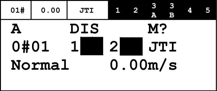
- During the self-learning period, only one in-car call is recorded per run.
- If a call is made at a floor without an elevator entrance, the elevator will arrive at that floor, but the car door will not open. To learn the LOP on the rear entrance side with the rear door open, enter a new in-car call on the same floor.
► Car: Enter the car.
► CAR.COP: Call the elevator from inside the car to the lowest floor.
– The car moves to the ground floor.
► Car: The elevator car door opens.
– If using selective door opening control: Opens the entrance side car door to enter the car and call the elevator.
– If using parallel door opening control: Opens the first entrance side car door.
► Car: Exit the car within 12 seconds after the car door is fully open.
► If there is only one button, press and hold the hall call button or the only available button until you receive the following indications:
– COP beeps three times.
– Indicator lights or pre-selected running arrows on both hall call buttons illuminate for approximately three seconds.
– If there is an LCUX on the floor, COP will beep twice more.
► Car: Enter the car.
► CAR.COP: Enter the car call:
To the other side of the same floor:
– If using selective door opening control, to the other entrance side of the same floor.
– If using parallel door opening control, to the same floor.
To the next adjacent floor.
► Perform the same steps until self-learning includes all peripheral devices.
► Car: Proceed to the floor closest to the control cabinet.
► HMI: Stop LOP self-learning mode.
HMI: Commands → Teach-in LOP → OFF → OK.
► AS.SCMAIN.HMI: Press the reset button.
- Scanning process stops: Scan information disappears from the fourth line of the HMI.
► HMI: Save the configuration on the peripheral PCBA.
HMI: Commands → FreezeNodeTr → OK.
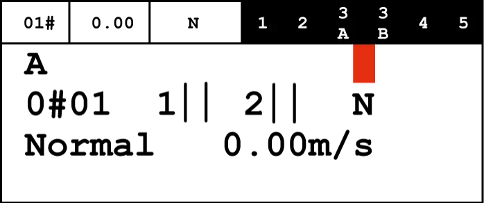
► HMI: Check the results of completed steps.
The top-left LCD segment must display either an empty field (" ") or an exclamation mark (!").
| Mark | State | Explanation |
| ? | ON | The freeze is not yet complete. |
| ? | Blinking | Execute freeze command |
| ! | ON | The freeze command has been completed, and there are changes compared to the previous one. |
| ! | Blinking | The freeze command failed. |
| None | - | The freeze command has been completed, and there are no changes from the last one. |
► Car: Proceed to each floor and ensure:
– All hall call buttons are functioning correctly.
– All location indicators and directional arrows are functioning correctly.
3. Debugging LIP Nodes Without LOPs
This chapter provides an alternative approach compared to the previous chapter. Use this information if the elevator has LIPs but no LOPs.
The self-learning of LIP nodes is performed in a server room or near a control cabinet in a server room. Nodes are connected to the bus one by one via LIP self-learning cables. This is an optional feature. The cable connects the LIP to SCMAIN.LOP.
► AS: Set JH to OFF.
► AS.SCMAIN.LOP: Disconnect the LOP connector from the hoistway wiring.
► Move all LIPs to the control cabinet.
► In the building interface box: Ensure that the CFG switches of the BIOGIO PCBA (up to three units) are set to different values, as shown below:
| Hardware Name | Software Name | CFG1 | CFG2 |
| GIO1 | E9 | OFF | ON |
| GIO2 | EA | ON | OFF |
| GIO3 | EB | ON | ON |
► Move to the control cabinet.
► Select one of the LIPs and connect it to the push-button switch in LIP.DE-U, which is provided as a component of the "LIP Self-Learning Cable Kit." This kit is supplied with the control cabinet.
► Connect the LIP to the BIO cable, which is also a component of the same kit.
► AS.SCMAIN.LOP: Insert the other end of the BIO cable.
► AS.JH: Set JH to ON.
► Before starting self-learning, remove all floor access restrictions.
– Floors with access restrictions are not included during self-learning.
► HMI: Move the car to a floor where access to the control cabinet is possible.
HMI: Commands → Car call → Floor → Entry side → OK.
► AS.SCMAIN.HMI: Press the reset button.
- Scanning process stops: Scan information disappears from the fourth line of the HMI.
► HMI: Start the self-learning process.
HMI: Commands → Teach-in → LOP Teach-in → ON → OK.
- The car door opens and remains open.
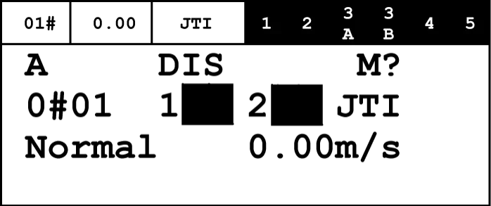
► HMI: Enter the lowest floor in-car call that requires LIP self-learning.
HMI: ESC+OK → Floor → Entry side → OK.
The car moves to that floor.
► Car: Elevator opens car door:
– If selective door opening control: Opens the entry side car door for the in-car call.
– If parallel door opening control: Opens the first entry side car door.
► After the car door is displayed as open on the HMI, press and hold the button for 12 seconds or less until the following indications are obtained:
– The button indicator light illuminates for approximately three seconds.
– The LIP pre-selection run arrow also illuminates for three seconds.
► LIP: Identifies the LIP by floor and provided access permissions.
► Remove the LIP and install a new one.
► HMI: If a second entry is available, enter another in-car call on the same floor:
– If selective door opening control is used, proceed to the other entry side.
– If using parallel door opening control, proceed to the first entrance side.
HMI: ESC+OK → Floor → EntrySide → OK.
► Repeat the same process until all LIPs have completed self-learning and can recognize the floor and entrance side.
► HMI: After completing this process, stop the self-learning mode.
HMI: Commands → Teach-in → LOP Teach-in → OFF → OK.
► LIP: Install the LIP to the designated floor and access it again to connect it to the bus.
► AS.SCMAIN.HMI: Press the reset button.
- Scanning process stops: Scan information disappears from the fourth line of the HMI.
► HMI: Save the configuration on the peripheral PCBA.
HMI: Commands → FreezeNodeTr → OK.
► HMI: Check the results of completed steps.
The top-left LCD segment must not display " " (empty field) or "!".
► Car: Proceed to each floor and ensure:
– All hall/station calls have been accepted.
– The location indicator and pre-selected direction arrow (if any) are functioning correctly.
4. Debugging LIP nodes with shared LOPs
This chapter covers additional operational steps that need to be completed before the node commissioning process when two elevators are using the same LOP.

► Determine which elevator has a node connected to:
– The DE1 connector on the LOPBG PCBA (FI GS), or
– The A-XDE-D/U connector on the BS PCBA (third-party peripheral).
► Identify elevator A.
► Identify another elevator sharing the call bar as elevator B.
► Elevator A: Set JH to ON.
► Elevator B: Set JH to OFF.
– If the main switch cannot be disconnected, unplug the SCMAIN.LOP connector from elevator B.
► Complete the self-learning process for elevator A, as shown in "BIO Bus Debugging for Hall Peripherals".
► Ensure that the hall call bar of elevator A is functioning correctly.
► Elevator A: Set JH to OFF.
– If the main switch cannot be disconnected, unplug the SCMAIN.LOP connector from elevator A.
► Elevator B: Set JH to ON.
► Complete the self-learning process of Elevator B, as shown in "BIO Bus Debugging of Hall/Station Peripherals".
► Ensure elevator B's hall call button is functioning correctly.
► Elevator A: Set JH to ON.
– If the main switch cannot be connected, insert SCMAIN.LOP into elevator A.
5. Debugging the CAN bus node
► All Floor CDPs: Ensure the CDP's lobby bus is connected to the PCBA CAN connector.
► All Floor CDPs: Ensure the CDP PCBA has the following settings:
– The high-position rotary switch (tens digit) and low-position rotary switch (units digit) settings are consistent with the floor level.
– The SZ switch setting is consistent with the entrance side.
– The terminal switch is set to OFF.
► All Floor ZRTLs: Ensure the ZRTL is not connected to the PCBA CAN connector's lobby bus.
► All Floor ZRTLs: Ensure the ZRTL terminal switch is set to ON in the following terminals:
– The bottom floor front entrance side, in elevators with only one entrance side.
– The top floor rear entrance side, in elevators with two entrance sides.
► Ensure all other ZRTL terminal switches are set to OFF.
► All floor BIBs (Building Interface Boxes): Ensure the CANGIO PCBA has the following settings:
– Set the node ID rotary switch to a different position (0 to F) on each board.
– Set the baud rate switch to 50.
– Set the TERM switch in all PCBAs to OFF.
There can be a maximum of 16 CANGIO PCBAs.
► AS.JH: Set JH to OFF.
► AS.SCMAIN.CANL: Insert the CANL connector.
► AS.JH: Set JH to ON.
Scanning process stops: Scan information disappears from the fourth line of the HMI.
► HMI: Start the input/output configuration process.
HMI: Command → Program IO function → OK.
- Displays a drop-down list of all PCBA types, containing configurable inputs/outputs.
► HMI: Ensure CANGIO is available.
- Do not program IO functions at this time.
► HMI: Put the elevator into reserved service mode.
HMI: Commands → Services → JRV → ON → OK.
► HMI: Enter the in-car call for the floor where the car entrance is located.
HMI: ESC+OK → Floor → Entry side → OK.
► Car: Proceed to each floor and ensure:
– Insert the relevant ZRTL.
– Commission it as shown in K 604085.
► AS.SCMAIN.HMI: Press the reset button.
- Scan process stops: Scan information disappears from the fourth line of the HMI.
► HMI: Save the configuration to the peripheral PCBA.
HMI: Commands → FreezeNodeTr → OK.
► HMI: Check the results of the completed steps.
The upper left LCD segment displays "!".
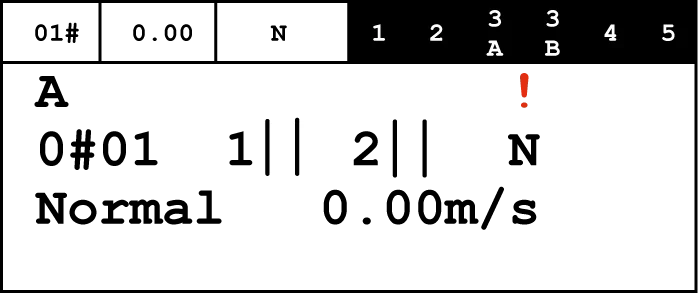
► Car: Proceed to each floor to ensure that ZRTL and CDP are working correctly.


