
1. User Interface
1.1 HMI User Interface
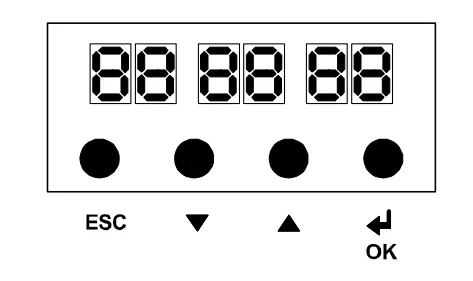
| Button | Function |
| ESC | Exit the current menu / navigate to the previous menu (without saving any content). |
| UP/DOWN | Move within the menu (modify the menu) to change its value. |
| OK | Confirm the input value to proceed to the next menu level. Note: When the maintenance mode is active (DIP switch 7 on SCIC), the OK button functions as the "DFM-U/D" button, controlling the cAr's upward and downward movement. |
1.2.Main menu structure
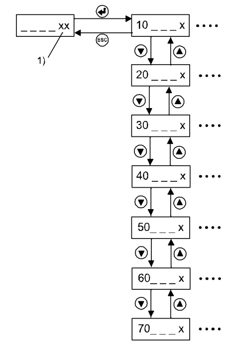
1) Actual floor
| Menu function | |
| 10 | Special commands, such as reset, learning operation, and in-car call... |
| 20 | Automated (assisted) acceptance testing |
| 30 | Status and system information (Requires software version ≥ V9.21.x) |
| 40 | Configuration |
| 50 | Diagnostics, Fault History |
| 60 | Statistics |
| 70 | ACVF monitoring (Biodyn xx C BR, Vacon NXP) |
1.3 COP as a user interface
① Activate elevator control configuration mode
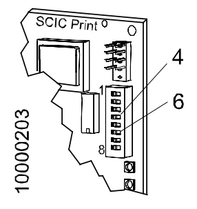
On the SCIC board:
- DIP switch 6 on = Configuration mode activated
- DIP switch 4 on = Fault code indication.
(Use "<>" to scroll through the last 10 faults in the log.)
② Display and operation
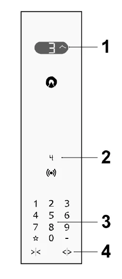
1) Status display during configuration:
CF = Configuration Mode
PA = Parameter
UL = Value (Input Value)
LE = Floor (Floor)
Cd = Countdown
LC = LOP Count
Ac = Accepted (Confirmed Input)
Br = JAB Detected
Er = Fault
FL = Floor
rL = Reference Load
Ld = Load (Actual Load)
CL = Calibration
2) Value of the active state. For example,
For rL: 32 = 320 kg
3) Keyboard (Key arrangement is also used for COP5)
4) "<>" = "Enter" key
The configuration mode can be turned on and off by using the key sequence "-" and "<>" as long as DIP switch 6 is active.
2. Configuration
1. Control Parameters (Menu 40)
1.1 Basic Principles
Elevator Control Configuration Using HMI
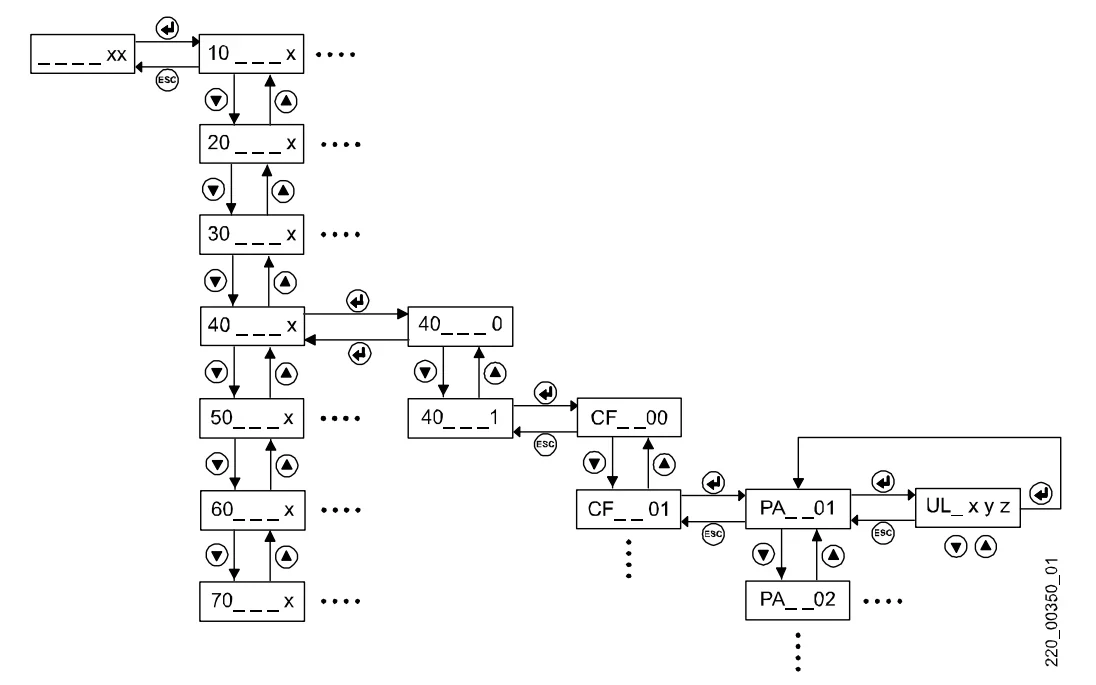 Enter configuration mode
| User Operations | Display | |
| HMI displays the actual floor of the elevator car. | xy | |
| 1 | Press the "OK" button on the HMI. | 10____ |
| 2 | Use the UP/DOWN keys to navigate to menu 40. | 40____ |
| 3 | Press "OK" to confirm. | 40___0 |
| 4 | Use the UP/DOWN keys to switch from "0" to "1" to activate configuration mode. | 40___1 |
| 5 | Press the "OK" button to confirm. The car will then travel to the configuration floor and open the door. System configuration is now ready. | CF__01 |
Change a parameter
| User Operations | Display | |
| System configuration is ready. | CF__01 | |
| 1 | Use the UP/DOWN keys to select the main menu CF you want to configure. Press the OK button to confirm the selection. → The HMI will then display the first submenu PA. | PA__01 |
| 2 | Use the UP/DOWN keys to select the submenu PA you want to configure. Press the OK button to confirm the selection. → The HMI will display the actual stored value VL. | VL_xyz |
| 3 | Press the OK button to change the first digit of the value. → The number of digits that can be changed will flash. | VL_xyz |
| 4 | Press the OK button to confirm the changed digit value and move to the next digit. Repeat steps 8 and 9 until the secondary menu PA reappears. | PA__xy |
Exit configuration mode
| User Operations | Display | |
| 1 | Press the ESC button until the HMI displays 40 _ _ _ 1 | 40 _ _ _ 1 |
| 2 | Use the UP/DOWN keys to navigate to 40 _ _ _ 0 and confirm with the "OK" button. → The top-level menu reappears. | 40 _ _ _ _ |
| 3 | Use the UP/DOWN keys to navigate to 40 _ _ _ 0 and confirm with the "OK" button. → The top-level menu reappears. | 40 _ _ _ _ |
| 4 | Press the ESC key. The HMI will then display the actual floor number again. | ___xyz |
Remark: Configuration mode can also be exited by pressing "-" and "DTO" in sequence on COP.


