
1. elevator Fault Investigation Basic Workflow
1.1 Receiving Fault Reports and Collecting Information
-
Key Steps:
-
Receive Fault Reports: Obtain initial descriptions from the reporting pArty (property managers, passengers, etc.).
-
Information Collection:
-
Record fault phenomena (e.g., "elevator stops suddenly," "abnormal noise").
-
Note occurrence time, frequency, and triggering conditions (e.g., specific floors, time periods).
-
-
Information Verification:
-
Cross-check non-professional descriptions with technical expertise.
-
Example: "Elevator vibration" may indicate mechanical misalignment or electrical interference.
-
-
1.2 On-Site Elevator Status Inspection
Classify elevator status into three categories for targeted actions:
1.2.1 Elevator Unable to Operate (Emergency Stop)
-
Critical Checks:
-
P1 Board Fault Codes:
-
Immediately record the 7-segment display (e.g., "E5" for main circuit failure) before power-off (codes reset after power loss).
-
Use the MON rotary potentiometer to retrieve codes (e.g., set MON to "0" for II-type elevators).
-
-
Control Unit LEDs:
-
Verify status of drive board LEDs, safety circuit indicators, etc.
-
-
Safety Circuit Testing:
-
Measure voltage at key nodes (e.g., hall door locks, limit switches) using a multimeter.
-
-
1.2.2 Elevator Operating with Faults (Intermittent Issues)
-
Investigation Steps:
-
Historical Fault Retrieval:
-
Use maintenance computers to extract recent fault logs (up to 30 records).
-
Example: Frequent "E35" (emergency stop) with "E6X" (hardware fault) suggests encoder or speed limiter issues.
-
-
Signal Monitoring:
-
Track input/output signals (e.g., door sensor feedback, brake status) via maintenance computers.
-
-
1.2.3 Elevator Operating Normally (Latent Faults)
-
Proactive Measures:
-
Auto-Reset Faults:
-
Check overload protection triggers or temperature sensors (e.g., clean inverter cooling fans).
-
-
Signal Interference:
-
Inspect CAN bus terminal resistors (120Ω) and shield grounding (resistance <1Ω).
-
-
1.3 Fault Handling and Feedback Mechanism
1.3.1 If Fault Persists
-
Documentation:
-
Complete a Fault Inspection Report with:
-
Device ID (e.g., contract number "03C30802+").
-
Fault codes, input/output signal status (binary/hex).
-
Photos of control panel LEDs/P1 board displays.
-
-
Escalation:
-
Submit logs to technical support for advanced diagnosis.
-
Coordinate spare parts procurement (specify G-numbers, e.g., "GCA23090" for inverter modules).
-
-
1.3.2 If Fault Resolved
-
Post-Repair Actions:
-
Clear Fault Records:
-
For II-type elevators: Restart to reset codes.
-
For IV-type elevators: Use maintenance computers to execute "Fault Reset."
-
-
Client Communication:
-
Provide a detailed report (e.g., "Fault E35 caused by oxidized hall door lock contacts; recommend quarterly lubrication").
-
-
1.4. Key Tools and Terminology
-
P1 Board: Central control panel displaying fault codes via 7-segment LEDs.
-
MON Potentiometer: Rotary switch for code retrieval on II/III/IV-type elevators.
-
Safety Circuit: A series-linked circuit including door locks, overspeed governors, and emergency stops.
2. Core Troubleshooting Techniques
2.1 Resistance Measurement Method
Purpose
To verify circuit continuity or insulation integrity.
Procedure
-
Power Off: Disconnect the elevator’s power supply.
-
Multimeter Setup:
-
For analog multimeters: Set to the lowest resistance range (e.g., ×1Ω) and calibrate zero.
-
For digital multimeters: Select "Resistance" or "Continuity" mode.
-
-
Measurement:
-
Place probes on both ends of the target circuit.
-
Normal: Resistance ≤1Ω (continuity confirmed).
-
Fault: Resistance >1Ω (open circuit) or unexpected values (insulation failure).
-
Case Study
-
Door Circuit Failure:
-
Measured resistance jumps to 50Ω → Check for oxidized connectors or broken wires in the door loop.
-
Cautions
-
Disconnect parallel circuits to avoid false readings.
-
Never measure live circuits.
2.2 Voltage Potential Measurement Method
Purpose
Locate voltage anomalies (e.g., power loss, component failure).
Procedure
-
Power On: Ensure the elevator is energized.
-
Multimeter Setup: Select DC/AC voltage mode with appropriate range (e.g., 0–30V for control circuits).
-
Step-by-Step Measurement:
-
Start from the power source (e.g., transformer output).
-
Trace voltage drop points (e.g., 24V control circuit).
-
Abnormal Voltage: Sudden drop to 0V indicates an open circuit; inconsistent values suggest component failure.
-
Case Study
-
Brake Coil Failure:
-
Input voltage: 24V (normal).
-
Output voltage: 0V → Replace the faulty brake coil.
-
2.3 Wire Jumping (Short-Circuit) Method
Purpose
Quickly identify open circuits in low-voltage signal paths.
Procedure
-
Identify Suspected Circuit: E.g., door lock signal line (J17-5 to J17-6).
-
Temporary Jumper: Use insulated wire to bypass the suspected open circuit.
-
Test Operation:
-
If the elevator resumes normal operation → Fault confirmed in the bypassed section.
-
Cautions
-
Prohibited Circuits: Never short safety circuits (e.g., emergency stop loops) or high-voltage lines.
-
Immediate Restoration: Remove jumpers after testing to avoid safety hazards.
2.4 Insulation Resistance Comparison Method
Purpose
Detect hidden ground faults or insulation degradation.
Procedure
-
Disconnect Components: Unplug the suspected module (e.g., door operator board).
-
Measure Insulation:
-
Use a 500V megohmmeter to test each wire’s insulation resistance to ground.
-
Normal: >5MΩ.
-
Fault: <1MΩ → Locate damaged insulation (e.g., bridgehead cable abrasion).
-
Case Study
-
Repeated Door Operator Burnout:
-
Insulation resistance of a signal line drops to 10kΩ → Replace the shorted cable.
-
2.5 Component Replacement Method
Purpose
Verify suspected hardware failures (e.g., drive boards, encoders).
Procedure
-
Pre-Replacement Checks:
-
Confirm peripheral circuits are normal (e.g., no short circuits or voltage spikes).
-
Match component specifications (e.g., G-number: GCA23090 for specific inverters).
-
-
Swap and Test:
-
Replace the suspected part with a known-good component.
-
Fault Persists: Investigate related circuits (e.g., motor encoder wiring).
-
Fault Transfers: Original component is defective.
-
Cautions
-
Avoid replacing components under power.
-
Document replacement details for future reference.
2.6 Signal Tracing Method
Purpose
Resolve intermittent or complex faults (e.g., communication errors).
Tools Required
-
Maintenance computer (e.g., Mitsubishi SCT).
-
Oscilloscope or waveform recorder.
Procedure
-
Signal Monitoring:
-
Connect the maintenance computer to the P1C port.
-
Use the Data Analyzer function to track signal addresses (e.g., 0040:1A38 for door status).
-
-
Trigger Setup:
-
Define conditions (e.g., signal value = 0 AND signal fluctuation >2V).
-
Capture data before/after fault occurrence.
-
-
Analysis:
-
Compare signal behavior during normal vs. faulty states.
-
Case Study
-
CAN Bus Communication Failure (EDX code):
-
Oscilloscope shows noise on CAN_H/CAN_L → Replace shielded cables or add terminal resistors.
-
2.7.Summary of Method Selection
| Method | Best For | Risk Level |
|---|---|---|
| Resistance Measurement | Open circuits, insulation faults | Low |
| Voltage Potential | Power loss, component defects | Medium |
| Wire Jumping | Rapid verification of signal paths | High |
| Insulation Comparison | Hidden ground faults | Low |
| Component Replacement | Hardware validation | Medium |
| Signal Tracing | Intermittent/software-related faults | Low |
3. Elevator Fault Diagnosis Tools: Categories and Operational Guidelines
3.1 Specialized Tools (Mitsubishi Elevator-Specific)
3.1.1 P1 Control Board and Fault Code System
-
Functionality:
-
Real-Time Fault Code Display: Uses a 7-segment LED to show fault codes (e.g., "E5" for main circuit failure, "705" for door system failure).
-
Historical Fault Retrieval: Some models store up to 30 historical fault records.
-
-
Operation Steps:
-
Type II Elevators (GPS-II): Rotate the MON potentiometer to "0" to read codes.
-
Type IV Elevators (MAXIEZ): Set MON1=1 and MON0=0 to display 3-digit codes.
-
-
Case Example:
-
Code "E35": Indicates an emergency stop triggered by speed governor or safety gear issues.
-
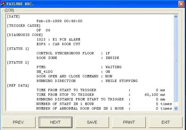
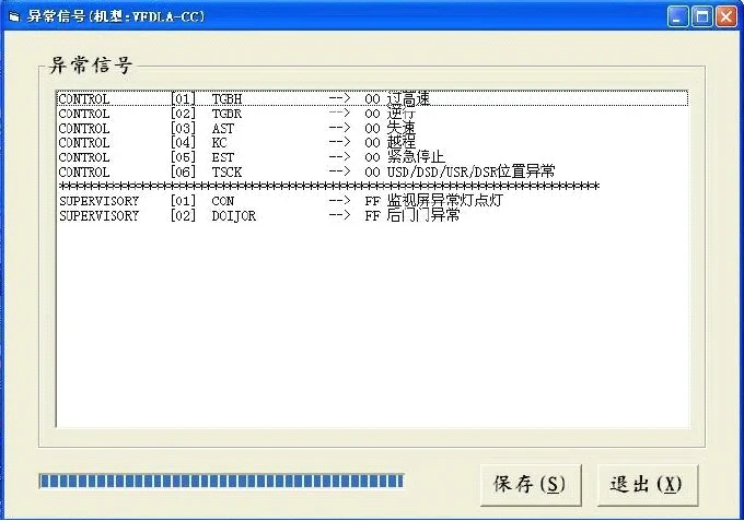
3.1.2 Maintenance Computer (e.g., Mitsubishi SCT)
-
Core Functions:
-
Real-Time Signal Monitoring: Track input/output signals (e.g., door lock status, brake feedback).
-
Data Analyzer: Capture signal changes before/after intermittent faults by setting triggers (e.g., signal transitions).
-
Software Version Verification: Check elevator software versions (e.g., "CCC01P1-L") for compatibility with fault patterns.
-
-
Connection Method:
-
Connect the maintenance computer to the P1C port on the control cabinet.
-
Select functional menus (e.g., "Signal Display" or "Fault Log").
-
-
Practical Application:
-
Communication Fault (EDX Code): Monitor CAN bus voltage levels; replace shielded cables if interference is detected.
-
3.2 General Electrical Tools
3.2.1 Digital Multimeter
-
Functions:
-
Continuity Test: Detect open circuits (resistance >1Ω indicates a fault).
-
Voltage Measurement: Verify 24V safety circuit power supply and 380V main power input.
-
-
Operational Standards:
-
Disconnect power before testing; select appropriate ranges (e.g., AC 500V, DC 30V).
-
-
Case Example:
-
Door lock circuit voltage reads 0V → Inspect hall door lock contacts or oxidized terminals.
-
3.2.2 Insulation Resistance Tester (Megohmmeter)
-
Function: Detect insulation breakdown in cables or components (standard value: >5MΩ).
-
Operation Steps:
-
Disconnect power to the tested circuit.
-
Apply 500V DC between the conductor and ground.
-
Normal: >5MΩ; Fault: <1MΩ.
-
-
Case Example:
-
Door motor cable insulation drops to 10kΩ → Replace worn bridgehead cables.
-
3.2.3 Clamp Meter
-
Function: Non-contact measurement of motor current to diagnose load anomalies.
-
Application Scenario:
-
Traction motor phase imbalance (>10% deviation) → Check encoder or inverter output.
-
3.3 Mechanical Diagnostic Tools
3.3.1 Vibration Analyzer (e.g., EVA-625)
-
Function: Detect vibration spectra from guide rails or traction machines to locate mechanical faults.
-
Operation Steps:
-
Attach sensors to the car or machine frame.
-
Analyze frequency spectra for anomalies (e.g., bearing wear signatures).
-
-
Case Example:
-
Vibration peak at 100Hz → Inspect guide rail joint alignment.
-
3.3.2 Dial Indicator (Micrometer)
-
Function: Precision measurement of mechanical component displacement or clearance.
-
Application Scenarios:
-
Brake Clearance Adjustment: Standard range 0.2–0.5mm; adjust via set screws if out of tolerance.
-
Guide Rail Verticality Calibration: Deviation must be <1mm/5m.
-
3.4 Advanced Diagnostic Equipment
3.4.1 Waveform Recorder
-
Function: Capture transient signals (e.g., encoder pulses, communication interference).
-
Operation Workflow:
-
Connect probes to target signals (e.g., CAN_H/CAN_L).
-
Set trigger conditions (e.g., signal amplitude >2V).
-
Analyze waveform spikes or distortions to locate interference sources.
-
-
Case Example:
-
CAN bus waveform distortion → Verify terminal resistors (120Ω required) or replace shielded cables.
-
3.4.2 Thermal Imaging Camera
-
Function: Non-contact detection of component overheating (e.g., inverter IGBT modules, motor windings).
-
Key Practices:
-
Compare temperature differences between similar components (>10°C indicates an issue).
-
Focus on hotspots like heat sinks and terminal blocks.
-
-
Case Example:
-
Inverter heat sink temperature reaches 100°C → Clean cooling fans or replace thermal paste.
-
3.5 Tool Safety Protocols
3.5.1 Electrical Safety
-
Power Isolation:
-
Perform Lockout-Tagout (LOTO) before testing main power circuits.
-
Use insulated gloves and goggles for live testing.
-
-
Short-Circuit Prevention:
-
Jumpers are only allowed for low-voltage signal circuits (e.g., door lock signals); never use on safety circuits.
-
3.5.2 Data Recording and Reporting
-
Standardized Documentation:
-
Record tool measurements (e.g., insulation resistance, vibration spectra).
-
Generate fault reports with tool findings and solutions.
-
4. Tool-Fault Correlation Matrix
| Tool Type | Applicable Fault Category | Typical Application |
|---|---|---|
| Maintenance Computer | Software/Communication Faults | Resolve EDX codes by tracing CAN bus signals |
| Insulation Tester | Hidden Shorts/Insulation Degradation | Detect door motor cable grounding faults |
| Vibration Analyzer | Mechanical Vibration/Guide Rail Misalignment | Diagnose traction motor bearing noise |
| Thermal Camera | Overheating Triggers (E90 Code) | Locate overheating inverter modules |
| Dial Indicator | Brake Failure/Mechanical Jams | Adjust brake shoe clearance |
5. Case Study: Integrated Tool Application
Fault Phenomenon
Frequent emergency stops with code "E35" (emergency stop sub-fault).
Tools and Steps
-
Maintenance Computer:
-
Retrieved historical logs showing alternating "E35" and "E62" (encoder fault).
-
-
Vibration Analyzer:
-
Detected abnormal traction motor vibrations, indicating bearing damage.
-
-
Thermal Camera:
-
Identified localized overheating (95°C) on an IGBT module due to clogged cooling fans.
-
-
Insulation Tester:
-
Confirmed encoder cable insulation was intact (>10MΩ), ruling out short circuits.
-
Solution
-
Replaced traction motor bearings, cleaned inverter cooling system, and reset fault codes.
Document Notes:
This guide systematically details core tools for Mitsubishi elevator fault diagnosis, covering specialized devices, general instruments, and advanced technologies. Practical cases and safety protocols provide actionable insights for technicians.
Copyright Notice: This document is based on Mitsubishi technical manuals and industry practices. Unauthorized commercial use is prohibited.


