
1. LeArning to run
1.1 Start the learning process
► HMI: Freeze NodeTree
HMI: Commands → FreezeNodeTree → OK.
► Ensure:
– Installers remain in front of the control cabinet.
– The car must be between the top and bottom hall stations.
► AS.HMI: Start Learning Operation.
HMI: Commands → Special Trips → JLF → OK.
► AS.SCPOW: Set JRH/JEM to NORMAL.
► HMI: Stop Installation and Running MOF.
HMI: Commands → Special Trips → MOF → OFF → OK.
The learning run has begun. During the learning run, the HMI displays the floor number for the corresponding location.
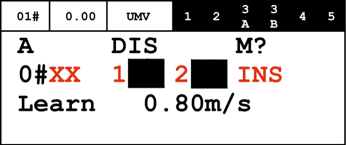
The learning process automatically stops in AC GSI self-learning mode.
► If the HMI displays "TMMB": Perform the configuration of the traction media.
If the elevator is equipped with a traction medium, it will be locked on the first floor hall, awaiting STM setup.

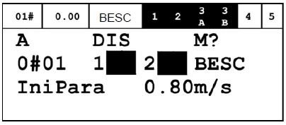
► If the HMI displays "BESC": Configure the emergency stop counter for the brake.
- If the elevator has the emergency stop counter function set, the elevator will be locked, awaiting its configuration.
1.2 Final check during learning operation
Learning process complete. HMI display:

► AS.HMI: Call the elevator from the car at both entrances to each floor.
HMI: Commands → Car call → Floor → Entry side → OK.
2. Weighing configuration
The commissioning steps described in this chapter apply to the KL66 load cell installed on the car and the AC FMW load cell installed at a fixed point.
► Ensure all counterweight blocks are added, as shown in the installation manual.
► Ensure the guide rails are correctly adjusted.
► Ensure the sliding or roller guide shoes are correctly adjusted within allowable tolerances. Installation must be performed according to the civil engineering drawings.
► If the load cell AC FMW is installed at a fixed point:
- AS.SCMAIN.LMS: Insert the load cell plug into the FIMO.
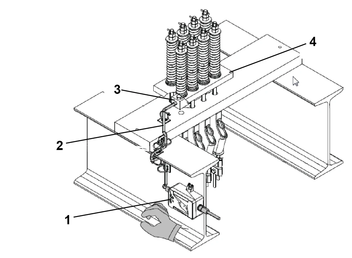
1 FIMO box 2 Sensor - FIMO box cable
3 AC FMW load cell 4 Rope end plate
► AS: Set the following switches to ON:
| JH | SIS | SIL |
2.1 0 kg configuration
► Ensure the car is empty.
► AS.HMI: Move the car to the floor where the calibration weights are located.
► AS.HMI: Activate the load cell LMS.
HMI: Commands → LM Disable → Enable → OK.
► AS.HMI: Open the car door.
HMI: Command → Door → Side 1 or 2 → Open → OK.
► After the car door is fully open:
AS.SCPOW: Set JRH/JEM to INSPECTION.
– Keep the car door open during calibration.
► AS.HMI: Obtain the zero-load reference point.
HMI: Commands → LM Commiss CLC → Zero Load Calibration → OK.
The controller reads the load cell output and sets the zero-load point for the empty car.
► AS.HMI: Wait until the HMI displays "Success".
2.2 Configure reference load
Car: Place the calibration weights into the car.
- Car load 40...100%.
► AS.HMI: Input reference load
HMI: Commands → LM Commiss CLC (Weighing Calibration CLC)
→ Ref Load Cal (Reference Load Calibration).
- The HMI displays the input screen for the reference load value in kg.
- Set the new reference load value → OK.
- The controller reads the load cell output and sets the reference load point using the calibration weights.
► HMI: Wait until the HMI displays "Success".
► Car: Remove the load from the car.
► Car: Ensure the car is empty.
► AS.HMI: Start KFM and stop outbound calls.
HMI: Command → Special trips → KFM → ON → OK
► AS.SCPOW: Set JRH/JEM to NORMAL.
– Car doors close.
► AS.HMI: Begin collecting floor-related zero-load calibration values. This is related to the compensation chain.
HMI: Command → LM Compmiss CLC → FloorAdjTravel → Compensation chain → Yes/No → OK
– The elevator begins calibration runs for each floor to obtain the zero-load value for each floor.
– The HMI displays “FloorAdjTravel = Success” and the maximum deviation value, i.e., the floor with the maximum deviation.
► AS.HMI: Press the ESC button to stop CLC commissioning.
► AS.HMI: Reads weighing parameter values and records them on the controller label (parameter change record).
HMI: Status → LM Calib Data → OK.
Zero Load Frequency:
– Zero Load Frequency 1 (Hz)
– Zero Load Frequency 2 (Hz).
Reference Load Frequency:
– Reference Load (kg)
– Reference Load Frequency 1 (Hz)
– Reference Load Frequency 2 (Hz).
► AS.HMI: Stops KFM and starts outbound calls.
HMI: Command → Special Trips → KFM → OFF → OK.
2.3 Configure minimum load
Minimum Load Adjustment
The weighing system's nonlinearity and insufficient resolution prevent it from accurately identifying smaller loads. This can disable in-car calls or cause standby power management malfunctions. The next step is to adjust the control unit's recognition threshold to 50 kg to eliminate these limitations.
► AS.HMI: Activate reserved service mode.
HMI: Commands → Services → Service JRV → ON → OK.
► Car: Place a 50 kg load in the center of the car.
► AS.HMI: Access load and frequency.
HMI: Status → LM Load and frequency
► HMI: Enter the in-car call for each floor.
HMI: ESC+OK → Floor → Entry side → OK.
► Record the load value displayed when the elevator stops at each floor.
► Select the smaller recorded value.
► Store the smaller value.
HMI: Parameter → Car → Minimal Load → OK.
2.4 Overload Inspection
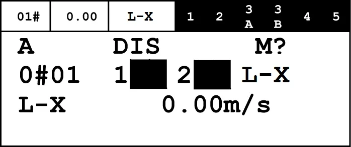
► Car: Loads a load equivalent to 110% of the car's load capacity in the car.
► AS.HMI: Ensures that the L-X indication is displayed.
► Car: Remove load from the car.
► AS.HMI: Check if "L-X" has changed to "Normal".
► AS.HMI: Stop the reserved service mode.
HMI: Commands → Services → Service JRV → OFF → OK.


