
1 Overview of Elevator Communication Systems
elevator communication circuits (OR) ensure reliable data exchange between critical components, directly impacting operational safety and efficiency. This guide covers CAN bus and RS-series protocols, providing technical insights for maintenance and SEO-optimized troubleshooting strategies.
1.1 CAN Bus System
Core Features
-
Topology: Multi-node bus network supporting full-duplex communication.
-
Electrical StandArds:
-
Differential Signaling: CAN_H (High) and CAN_L (Low) twisted-pair cables for noise immunity.
-
Voltage Levels: Dominant (CAN_H=3.5V, CAN_L=1.5V) vs. Recessive (CAN_H=2.5V, CAN_L=2.5V).
-
-
Priority Mechanism:
-
Lower ID values = Higher priority (e.g., ID 0 > ID 100).
-
Collision resolution via automatic node withdrawal.
-
Applications
-
Real-time safety monitoring
-
Group control coordination
-
Fault code transmission
Wiring Specifications
| Cable Type | Color Code | Termination Resistor | Max Length |
|---|---|---|---|
| Twisted Shielded Pair | CAN_H: Yellow | 120Ω (Both Ends) | 40m |
| CAN_L: Green |
1.2 RS-Series Communication Protocols
Protocol Comparison
| Protocol | Mode | Speed | Nodes | Noise Immunity |
|---|---|---|---|---|
| RS-232 | Point-to-Point | 115.2 kbps | 2 | Low |
| RS-485 | Multi-Drop | 10 Mbps | 32 | High |
Key Uses
-
RS-485: Hall call systems, car status feedback.
-
RS-232: Maintenance computer interfaces.
Installation Guidelines
-
Use twisted shielded cables (AWG22 or thicker).
-
Terminate bus ends with 120Ω resistors.
-
Avoid star topologies; prioritize daisy-chain connections.
1.3 Elevator Communication Architecture
Four Key Subsystems
-
Group Control: Coordinates multiple elevators via CAN bus.
-
Car Systems: Manages internal commands via RS-485.
-
Hall Stations: Handles external calls; requires hall Power boxes (H10-H20).
-
Auxiliary Functions: Firefighter access, remote monitoring.
Power Management
| Scenario | Solution | Configuration Tips |
|---|---|---|
| >20 Hall Nodes | Dual power (H20A/H20B) | Balance load (≤15 nodes/group) |
| Long Distance (>50m) | Signal repeaters | Install every 40m |
| High EMI Environments | Ferrite filters | Attach at bus endpoints |
1.4 Troubleshooting Guide
-
Basic Checks:
-
Measure bus voltage (CAN: 2.5-3.5V; RS-485: ±1.5-5V).
-
Verify termination resistors (120Ω for CAN/RS-485).
-
-
Signal Analysis:
-
Use oscilloscope to detect waveform distortion.
-
Monitor CAN bus load (<70% recommended).
-
-
Isolation Testing:
-
Disconnect nodes to identify faulty segments.
-
Replace suspected components (e.g., hall power boxes).
-
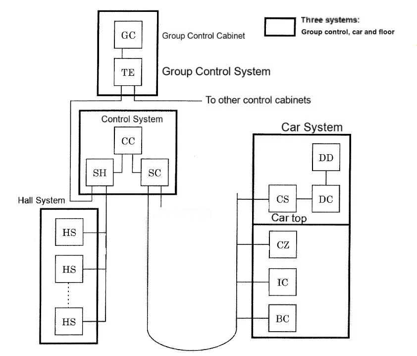
Figure 1: Elevator Communication System Diagram
2 General Troubleshooting Steps
Communication faults in elevator systems can manifest in diverse ways, but following a structured approach ensures efficient diagnosis and resolution. Below are optimized steps for identifying and resolving OR circuit issues, tailored for SEO and technical clarity.
2.1 Identify Faulty Communication Bus via P1 Board Error Codes
Key Actions:
-
Check P1 Board Codes:
-
Older systems: Generic codes (e.g., "E30" for communication errors).
-
Modern systems: Detailed codes (e.g., "CAN Bus Timeout" or "RS-485 CRC Error").
-
-
Prioritize Signal Isolation:
-
Example: A "Group Control Link Failure" code indicates CAN bus issues, while "Hall Call Timeout" points to RS-485 faults.
-
2.2 Inspect Power & Data Lines
Critical Checks:
-
Continuity Testing:
-
Use a multimeter to verify wire integrity. For long cables, create a loop with spare wires for accurate measurement.
-
-
Insulation Resistance:
-
Measure with a megohmmeter (>10MΩ for RS-485; >5MΩ for CAN bus).
-
Tip: High-frequency signals mimic short circuits if insulation degrades.
-
-
Twisted Pair Specifications:
-
Verify twist pitch (standard: 15–20mm for CAN; 10–15mm for RS-485).
-
Avoid non-standard cables—even short segments disrupt signal integrity.
-
2.3 Diagnose Node Issues via Status LEDs
Procedure:
-
Locate Faulty Nodes:
-
CAN nodes: Check "ACT" (activity) and "ERR" LEDs.
-
RS-485 nodes: Verify "TX/RX" blink rates (1Hz = normal).
-
-
Common LED Patterns:
LED State Interpretation ACT steady, ERR off Node functional ERR blinking CRC error or ID conflict ACT/RX off Power or signal loss
2.4 Verify Node Settings & Termination Resistors
Configuration Checks:
-
Node ID Validation:
-
Ensure IDs match floor assignments (e.g., Node 1 = 1st floor).
-
Mismatched IDs cause packet rejection or bus collisions.
-
-
Termination Resistors:
-
Required at bus endpoints (120Ω for CAN/RS-485).
-
Example: If the farthest node changes, relocate the resistor.
-
Common Issues:
-
Missing termination → Signal reflections → Data corruption.
-
Incorrect resistor value → Voltage drop → Communication failure.
2.5 Additional Considerations
-
Firmware Consistency:
-
All nodes (especially hall stations) must run identical software versions.
-
-
Hardware Compatibility:
-
Replace faulty boards with matching versions (e.g., R1.2 boards for R1.2 nodes).
-
-
Power Interference:
-
Test AC sources (e.g., lighting circuits) for EMI using a spectrum analyzer.
-
Install ferrite cores on communication cables near high-power devices.
-
3 Common Communication Faults
3.1 Fault: Car Floor Buttons Unresponsive
Possible Causes & Solutions:
| Cause | Solution |
|---|---|
| 1. Serial Signal Cable Fault | - Check for shorts/breaks in serial cables from car panel to car top station and control cabinet. - Use multimeter to test continuity. |
| 2. Control Panel Jumper Error | - Verify jumper/switch settings per wiring diagrams (e.g., door type, floor assignments). - Adjust potentiometers for signal strength. |
| 3. Special Modes Activated | - Disable firefighter/lock modes via P1 board. - Reset service switch to normal operation. |
| 4. Board Failure | - Replace faulty boards: P1, door control, car BC board, or car panel power supply. |
3.2 Fault: Hall Call Buttons Unresponsive
Possible Causes & Solutions:
| Cause | Solution |
|---|---|
| 1. Serial Cable Issues | - Inspect hall-to-landing station and landing-to-control cabinet cables. - Test with spare cables if needed. |
| 2. Group Control Errors | - Check group control connections (CAN bus). - Verify P1 board jumpers match elevator number. - Test GP1/GT1 boards in group control panel. |
| 3. Floor Potentiometer Misconfiguration | - Adjust FL1/FL0 settings per installation drawings. - Recalibrate floor position sensors. |
| 4. Board Failure | - Replace faulty hall call boards, landing station boards, or P1/group control boards. |
3.3 Fault: Auto-Cancel of Registered Calls During Operation
Possible Causes & Solutions:
| Cause | Solution |
|---|---|
| 1. Signal Interference | - Verify all grounding points (resistance <1Ω). - Separate communication cables from power lines (>30cm spacing). - Ground unused wires in flat cables. - Install ferrite cores or shielded conduits. |
| 2. Board Malfunction | - Replace serial communication boards (P1, car/hall panels). - Update firmware to latest version. |
Technical Tips for Maintenance
-
Cable Testing:
-
Use a time-domain reflectometer (TDR) to locate cable faults in long serial lines.
-
-
Grounding Check:
-
Measure voltage between communication cable shields and ground (<0.5V AC).
-
-
Firmware Updates:
-
Always match board firmware versions (e.g., P1 v3.2 with door control v3.2).
-


