
Introduction
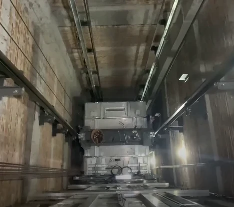
The elevator shaft is the central installation space for most of the elevator's major moving components.
The elevator cAr, counterweight, guide rails, wire ropes, traveling cable, landing doors and many safety-related components all operate within or connect directly to the shaft.
At the bottom of the shaft is the elevator pit, which provides the necessary space for buffers, safety equipment, inspection access and other components.
Before elevator installation begins, the shaft and pit must be inspected carefully.
A problem with the building structure, shaft dimensions, guide rail supports, landing openings, pit drainage or safety space can create significant difficulties later during installation and commissioning.
The supplied technical document separates the installation conditions into machine room, shaft, pit and landing-door requirements. It specifies requirements concerning shaft construction, openings, guide rail supports, shaft lighting, ventilation, pit drainage, buffers and safety space.
This article reorganizes those requirements into a practical guide for elevator installation contractors, technicians, engineers and maintenance professionals.
1. What Is an Elevator Shaft?
An elevator shaft is the vertical space in a building through which the elevator car and counterweight travel.
A conventional traction elevator typically contains:
- Elevator car
- Counterweight
- Guide rails
- Wire ropes
- Overspeed governor components
- Traveling cable
- Landing doors
- Safety-related equipment
The basic elevator structure shown in the supplied material identifies the car, counterweight, guide rails, landing doors, wire rope, safety gear, overspeed governor and buffer as important components of the elevator system.
Because so many components interact within the shaft, the shaft must be correctly prepared before installation.
2. Why Elevator Shaft Preparation Is Important
A shaft may look like a simple empty vertical space, but its dimensions and structural conditions directly affect elevator installation.
For example:
Incorrect shaft dimensions
→ difficult equipment installation
Poor guide rail supports
→ guide rail alignment problems
Incorrect landing openings
→ door installation problems
Insufficient pit depth
→ safety-space problems
Poor shaft lighting
→ difficult installation and maintenance
Water entering the pit
→ corrosion and electrical problems
Therefore, shaft inspection should be completed before elevator equipment is delivered to the site.
3. Elevator Shaft Structural Requirements
The supplied reference specifies that the shaft enclosure should have adequate structural strength and gives a reference concrete strength of 24 MPa for the shaft wall structure. It also discusses structural reinforcement and the use of suitable construction materials.
The exact structural requirements for a real project must be confirmed by:
- Building structural drawings
- Elevator design drawings
- Manufacturer requirements
- Local building regulations
- Applicable elevator standards
The elevator installation team should not independently change structural elements simply to make equipment fit.
4. Elevator Shaft Dimensions
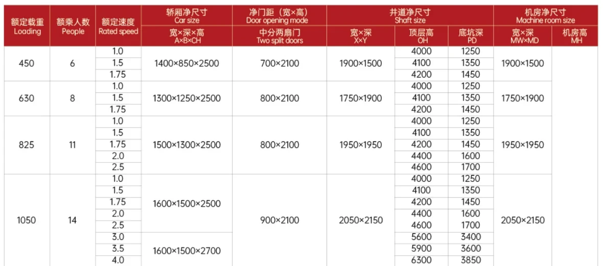
The shaft dimensions must correspond to the elevator design.
Important dimensions include:
- Shaft width
- Shaft depth
- Overhead space
- Pit depth
- Landing opening width
- Landing opening height
- Guide rail position
- Car position
- Counterweight position
The supplied material also states that shaft dimensions should be measured based on the minimum clear dimensions of the shaft.
This is important because construction tolerances can cause actual dimensions to differ from the original building drawings.
5. How to Inspect Elevator Shaft Dimensions
Before installation, technicians should measure the shaft at multiple locations.
Do not rely on a single measurement.
Check:
Shaft Width
Measure the clear width at different floors.
Shaft Depth
Measure from the front wall toward the rear wall.
Vertical Alignment
Check whether the shaft walls remain within the required construction tolerance.
Landing Openings
Check each floor individually.
Guide Rail Positions
Confirm that there is sufficient structural space for the guide rail brackets.
Overhead
Check the available space above the highest landing.
Pit
Check the pit depth and available safety space.
6. Elevator Shaft Landing Openings
Landing openings are critical because every floor must align with the elevator landing-door system.
The supplied reference states that elevator shafts should generally be enclosed by walls, floor and roof, while allowing necessary openings such as:
- Landing door openings
- Inspection and emergency access openings
- Fire-related openings where required
- Ventilation openings
- Permanent access between the shaft and machine room where applicable
Unnecessary openings should be avoided because they may affect safety, fire protection or shaft integrity.
7. Elevator Shaft Ventilation
The supplied material includes shaft ventilation requirements and states that ventilation openings should be arranged appropriately.
It also specifies that ventilation should communicate with the outside or an appropriate external area rather than simply connecting the shaft to unrelated rooms.
The actual design must follow the building and elevator requirements applicable to the project.
The key objective is to prevent the shaft from becoming an unsuitable environment for elevator equipment.
8. Elevator Shaft Lighting
Permanent shaft lighting is extremely important.
The supplied reference describes permanent lighting inside the shaft, including lighting near the upper and lower portions and intermediate lighting at appropriate intervals.
Good shaft lighting allows technicians to inspect:
- Guide rails
- Guide rail brackets
- Wire ropes
- Counterweight
- Car top
- Traveling cable
- Door equipment
- Safety devices
- Shaft wiring
Poor lighting can turn a relatively simple inspection into a difficult and unsafe task.
9. Elevator Guide Rail Supports
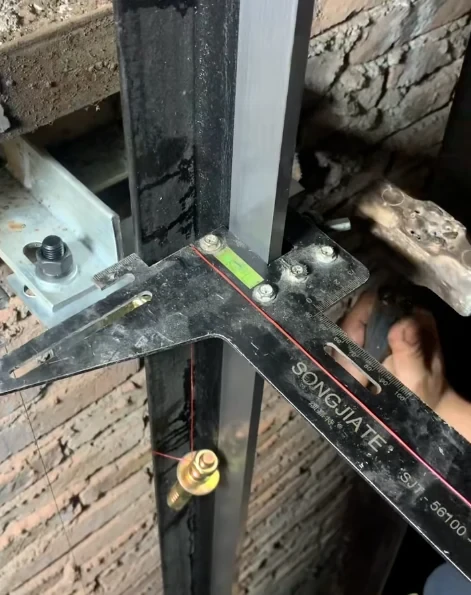
Guide rails are attached to the shaft structure through guide rail brackets.
The supplied installation requirements specify guide rail bracket arrangements, structural fixing and support requirements. It also discusses the fixing depth of expansion bolts and the need for suitable structural support.
Guide rail brackets must be:
- Correctly positioned
- Securely fixed
- Properly aligned
- Capable of supporting the designed loads
- Installed according to the elevator design
10. Elevator Guide Rail Installation
The guide rail system controls the vertical movement of:
- Elevator car
- Counterweight
The supplied material provides detailed installation-quality requirements for guide rails, including:
- Guide rail alignment
- Guide rail joints
- Bracket installation
- Rail working surfaces
- Relative position of car and counterweight rails
Guide rail installation is one of the most important mechanical installation processes inside the shaft.
11. Why Guide Rail Alignment Matters
If the guide rails are incorrectly installed, the elevator may experience:
- Car vibration
- Abnormal running noise
- Uneven movement
- Increased guide shoe wear
- Increased mechanical stress
- Poor ride comfort
This is why the installation team should measure guide rail alignment rather than relying only on visual inspection.
12. Guide Rail Joints
Guide rail joints need special attention.
The supplied material specifies requirements for guide rail joints and the treatment of unevenness at the working surfaces.
A poorly finished rail joint can cause the guide shoe to encounter a sudden mechanical change during operation.
Technicians should therefore inspect:
- Rail joint condition
- Joint fastening
- Working surface
- Alignment
- Burrs
- Uneven surfaces
13. Elevator Guide Shoes
The guide shoe is the interface between the elevator car or counterweight and the guide rail.
A guide shoe must work smoothly with the guide rail.
During installation, check:
- Correct guide shoe type
- Mounting position
- Fasteners
- Contact condition
- Alignment
- Lubrication requirements where applicable
Poor guide rail installation can accelerate guide shoe wear.
This is one reason why guide shoe and guide rail maintenance should always be considered together.
14. Counterweight Guide Rails
The counterweight also requires its own guide rail system.
The supplied document discusses the relative alignment and installation requirements between the car guide rails and counterweight guide rails.
The counterweight system should move smoothly without interference with:
- Shaft walls
- Brackets
- Traveling cable
- Other elevator components
15. Protection Between Multiple Elevators
Where multiple elevators share one shaft or adjacent shaft spaces, protection may be required between moving components.
The supplied material describes protective arrangements between elevator movement areas and discusses the required separation/protection conditions.
The exact arrangement must follow the elevator design and applicable regulations.
16. Elevator Landing Door Openings
Each landing opening must be checked before the landing door is installed.
Inspect:
- Opening width
- Opening height
- Wall condition
- Sill support
- Door-frame mounting points
- Relative position to the car
If the opening is incorrect, technicians may later need to make difficult structural adjustments.
It is therefore much better to discover the problem during the building inspection stage.
17. Elevator Landing Door Installation
The landing door system includes:
- Door frame
- Door panel
- Door sill
- Door rollers
- Door guide
- Door lock
- Door operating mechanism
The supplied installation-quality requirements include inspection of landing-door sills, panels, door locks, door rollers and related clearances.
18. Elevator Door Lock
The elevator door lock is one of the most important safety-related components in the landing-door system.
During installation, the door lock should be checked for:
- Correct installation
- Secure fastening
- Mechanical engagement
- Electrical contact
- Correct relationship with the door position
- Correct safety-circuit operation
A door may look mechanically correct while still having an electrical door-lock problem.
Therefore, visual inspection alone is not enough.
19. Elevator Door Sill
The door sill provides the lower guide/support area for the landing door.
The supplied material specifies requirements related to sill installation, levelness and clearances.
The sill should be:
- Secure
- Level
- Clean
- Properly aligned
- Free from deformation
Construction debris inside the sill groove can cause door movement problems.
20. Elevator Pit Requirements
The pit is the lowest part of the elevator shaft.
It provides space for components such as:
- Buffers
- Pit stop switch
- Safety equipment
- Counterweight-related equipment
- Inspection access
- Required safety clearance
The supplied reference specifically requires the pit to have appropriate structural construction, drainage provisions and a smooth floor condition.
21. Elevator Pit Drainage
Water is one of the major enemies of elevator equipment.
The supplied material requires appropriate pit drainage arrangements and states that the pit should not accumulate water.
Water in the pit can contribute to:
- Corrosion
- Cable deterioration
- Electrical insulation problems
- Sensor problems
- Safety-device problems
- Mechanical component damage
For this reason, pit waterproofing and drainage should be checked before elevator equipment is installed.
22. Elevator Pit Floor
The pit floor should be completed and reasonably level.
The reference material states that the pit floor should be smooth and level and that appropriate structural conditions must be provided.
The floor should also be kept clean during installation.
Do not allow:
- Standing water
- Loose concrete
- Construction waste
- Oil contamination
- Sharp debris
to remain in the pit.
23. Elevator Buffer Installation
The buffer is an important safety component installed at the bottom of the shaft.
The supplied installation requirements include buffer position and installation checks.
The buffer must be correctly positioned relative to:
- Elevator car
- Counterweight
- Pit floor
- Other shaft components
The exact buffer type depends on the elevator design.
24. Buffer Alignment
The buffer should be correctly aligned with the corresponding moving component.
For example:
Car buffer
should be positioned relative to the elevator car.
Counterweight buffer
should be positioned relative to the counterweight.
Incorrect positioning can affect the safety system and must be corrected before commissioning.
25. Elevator Pit Safety Space
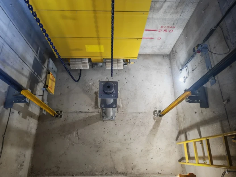
Adequate safety space must be available in the pit.
The supplied document specifies requirements concerning the clear space beneath the elevator car and related pit safety arrangements.
This space is especially important when technicians need to enter the pit for:
- Inspection
- Maintenance
- Adjustment
- Cleaning
- Component replacement
The required dimensions must be verified according to the actual elevator design and applicable code.
26. Pit Stop Switch
A pit stop switch provides an emergency stop function for work inside the pit.
The supplied installation requirements call for a manually operated, non-automatic-reset emergency stop switch in the pit.
The switch should be:
- Clearly identifiable
- Easily accessible
- Correctly wired
- Functionally tested
Technicians should verify the switch during commissioning and maintenance.
27. Elevator Pit Access
Safe access to the pit is essential.
Depending on the building and elevator design, this may involve:
- Fixed ladder
- Approved access arrangement
- Landing-door access
- Pit lighting
- Emergency stop device
Before entering the pit, technicians should follow the approved site safety procedure.
The separate safety material supplied with the project emphasizes controlled access to the pit, verification of the safety circuit, appropriate pit-door control and confirmation that the elevator is not moving before entering.
28. Elevator Shaft and Pit Electrical Wiring
Electrical cables inside the shaft require careful routing.
Typical shaft wiring may include:
- Traveling cable
- Door wiring
- Safety circuit wiring
- Shaft sensors
- Limit switches
- Communication cables
- Lighting circuits
The supplied installation-quality material requires cable routing to avoid interference with moving components and specifies appropriate support and arrangement.
29. Traveling Cable Installation
The traveling cable moves with the elevator car.
Therefore, it must have sufficient flexibility and correct routing.
The supplied reference requires that:
- The cable be properly secured
- The cable not contact the pit floor or car bottom after compression
- The cable not be tied in a way that creates abnormal deformation
- The cable route avoid moving components
Incorrect traveling-cable installation can eventually cause cable wear or intermittent electrical faults.
30. Shaft Cable Arrangement
Shaft cables should be routed so they do not interfere with:
- Car
- Counterweight
- Guide rails
- Door equipment
- Safety devices
- Wire ropes
The supplied material specifically requires cables to avoid crossing or interfering with wire ropes, door components, limit switches, sensors and counterweight equipment.
This is an important point that technicians should check during final installation inspection.
31. Elevator Shaft Cleanliness
The shaft should be cleaned before commissioning.
Remove:
- Concrete fragments
- Welding slag
- Dust
- Packaging materials
- Loose bolts
- Wire scraps
- Wood
- Oil
- Construction debris
Small objects inside the shaft can become dangerous when the elevator begins moving.
32. Elevator Shaft Safety During Installation
Working inside an elevator shaft involves several hazards:
- Falling from height
- Falling objects
- Moving equipment
- Electrical energy
- Mechanical energy
- Suspended loads
The supplied safety reference emphasizes fall protection, controlled shaft access, hazardous-energy control and protection against falling objects.
Installation work should therefore only be performed by properly trained and authorized personnel using approved procedures and equipment.
33. Guide Rail Installation Quality Checklist
Use the following checklist during guide rail installation.
Guide Rails
- Correct rail specification
- Correct position
- Correct vertical alignment
- Rail joints inspected
- Working surfaces clean
- No excessive burrs
- Fasteners secure
Brackets
- Correct spacing
- Secure fixing
- Structural support adequate
- No loose brackets
Guide Shoes
- Correct type
- Correct installation
- Proper alignment
- No abnormal interference
34. Elevator Shaft Inspection Checklist
Building
- Shaft structure complete
- Shaft dimensions checked
- Landing openings checked
- Guide rail supports ready
- Shaft enclosure complete
Lighting
- Permanent shaft lighting installed
- Upper area illuminated
- Lower area illuminated
- Intermediate lighting available
Mechanical
- Guide rails installed
- Guide rail brackets installed
- Counterweight rails installed
- Buffers installed
- Door sills installed
Electrical
- Traveling cable installed
- Shaft wiring secured
- Sensors installed
- Limit switches installed
- Safety circuit checked
Pit
- Pit clean
- Drainage checked
- Waterproofing checked
- Pit stop switch installed
- Required safety space available
- Buffer position checked
35. Common Elevator Shaft Problems
Problem 1: Shaft Too Narrow
Possible consequences:
- Guide rail installation difficulty
- Reduced clearances
- Car installation problems
- Counterweight interference
Problem 2: Incorrect Landing Opening
Possible consequences:
- Landing-door installation problems
- Door-frame adjustment
- Door sill alignment problems
Problem 3: Weak Guide Rail Support
Possible consequences:
- Rail movement
- Alignment problems
- Vibration
- Increased guide shoe wear
Problem 4: Poor Pit Drainage
Possible consequences:
- Water accumulation
- Corrosion
- Electrical faults
- Safety-device deterioration
Problem 5: Poor Cable Routing
Possible consequences:
- Cable wear
- Mechanical interference
- Intermittent electrical faults
36. Elevator Shaft and Spare Parts
The shaft contains many components that may eventually require replacement.
Common elevator spare parts associated with shaft equipment include:
- Guide shoe
- Guide rail components
- Door lock
- Door rollers
- Door stopper
- Limit switches
- Shaft sensors
- Traveling cable
- Buffer components
- Safety switches
- Electrical connectors
For maintenance companies, identifying the exact elevator model and component part number is essential before ordering replacement components.
37. Elevator Door Components and Spare Parts
The landing-door system is one of the most frequently serviced areas of an elevator.
Typical replacement components include:
Elevator Door Lock
Used as part of the landing-door locking and safety system.
Door Roller
Allows the door panel to move along its guide system.
Elevator Door Stopper
Used in certain door mechanisms to limit or control door movement.
Door Sill
Provides the lower guide/support surface.
Door Operator Components
Responsible for opening and closing the door.
These components should be selected according to the specific elevator model and door system.
38. Elevator Shaft Testing
After shaft installation is complete, technicians should perform appropriate checks before normal operation.
Possible checks include:
- Guide rail alignment
- Door operation
- Door lock
- Limit switches
- Safety switches
- Traveling cable movement
- Buffer condition
- Pit stop switch
- Shaft lighting
- Safety circuit
Professional elevator testing tools can help technicians verify electrical and mechanical conditions during commissioning.
39. Shaft Inspection Before Commissioning
A final shaft inspection should answer several questions:
Can the elevator move without interference?
Check the entire travel path.
Are the guide rails correctly installed?
Inspect alignment and joints.
Can the car and counterweight move safely?
Check clearances and cable routing.
Are all landing doors correctly installed?
Check sills, panels, rollers and elevator door lock operation.
Is the pit ready?
Check buffers, drainage, lighting, emergency stop and safety space.
Is the shaft clean?
Remove all unnecessary materials before test operation.
40. Recommended Elevator Shaft Installation Workflow
A practical workflow is:
Step 1 — Building Inspection
↓
Step 2 — Shaft Dimension Measurement
↓
Step 3 — Guide Rail Support Inspection
↓
Step 4 — Guide Rail Installation
↓
Step 5 — Car and Counterweight Installation
↓
Step 6 — Landing Door Installation
↓
Step 7 — Shaft Cable Installation
↓
Step 8 — Pit Equipment Installation
↓
Step 9 — Electrical and Safety Circuit Inspection
↓
Step 10 — Shaft Cleaning
↓
Step 11 — Commissioning
↓
Step 12 — Final Inspection
This sequence helps identify construction problems before they become expensive installation or commissioning problems.
Frequently Asked Questions
What are the main elevator shaft requirements?
Important requirements include appropriate shaft dimensions, structural strength, guide rail supports, landing openings, ventilation, lighting, cable routing and sufficient clearance for the elevator's moving components.
What are the main elevator pit requirements?
The pit should provide suitable structural conditions, drainage, buffers, safety devices, access, lighting and the required safety clearance.
Why is guide rail alignment important?
Guide rails guide the elevator car and counterweight. Incorrect alignment can contribute to vibration, noise, guide shoe wear and poor ride quality.
What is an elevator door lock?
An elevator door lock is part of the landing-door safety system. It confirms the required door-locking condition before the elevator is allowed to operate normally.
Why does the elevator pit need drainage?
Water can cause corrosion and electrical problems and may damage safety-related components. Proper drainage and waterproofing therefore help protect the elevator system.
What should be checked before entering an elevator pit?
Follow the approved site safety procedure. The supplied safety material emphasizes controlling the elevator, verifying safety-circuit conditions, using the required access method and confirming that the elevator cannot move unexpectedly.
What elevator spare parts are commonly used in the shaft?
Common components include guide shoes, door locks, door rollers, door stoppers, limit switches, sensors, traveling cables, buffer components and safety switches.
Conclusion
The elevator shaft and elevator pit form the physical environment in which most of the elevator's moving components operate.
Before elevator installation begins, the shaft dimensions, structural conditions, landing openings and guide rail supports should be carefully inspected.
During installation, special attention should be paid to:
- Guide rails
- Guide rail brackets
- Guide shoes
- Counterweight
- Landing doors
- Elevator door lock
- Traveling cable
- Shaft sensors
- Limit switches
- Buffers
- Pit stop switch
- Pit drainage
- Safety space
The supplied technical reference places particular emphasis on guide rail installation, shaft lighting, cable routing, landing-door installation, pit construction and buffer installation.
For an elevator installation contractor, the most important principle is simple:
Do not wait until commissioning to discover shaft problems. Measure, inspect and correct the shaft before the elevator equipment is fully installed.
Proper shaft preparation not only makes installation easier but can also reduce future problems involving guide shoe, door systems, electrical wiring and other elevator spare parts.


