
Table of Contents
1. Control Cabinet (Item 203) Settings
1.1 P1 Board Configuration (Models: P203758B000/P203768B000)
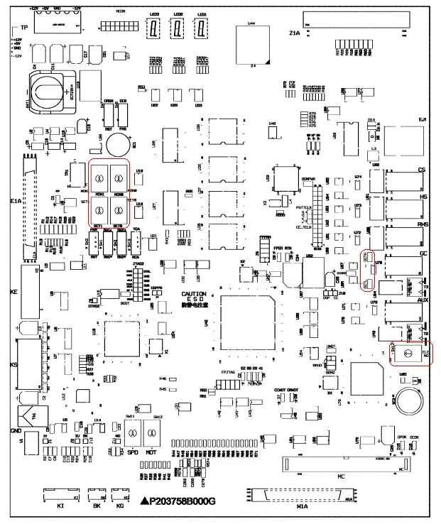
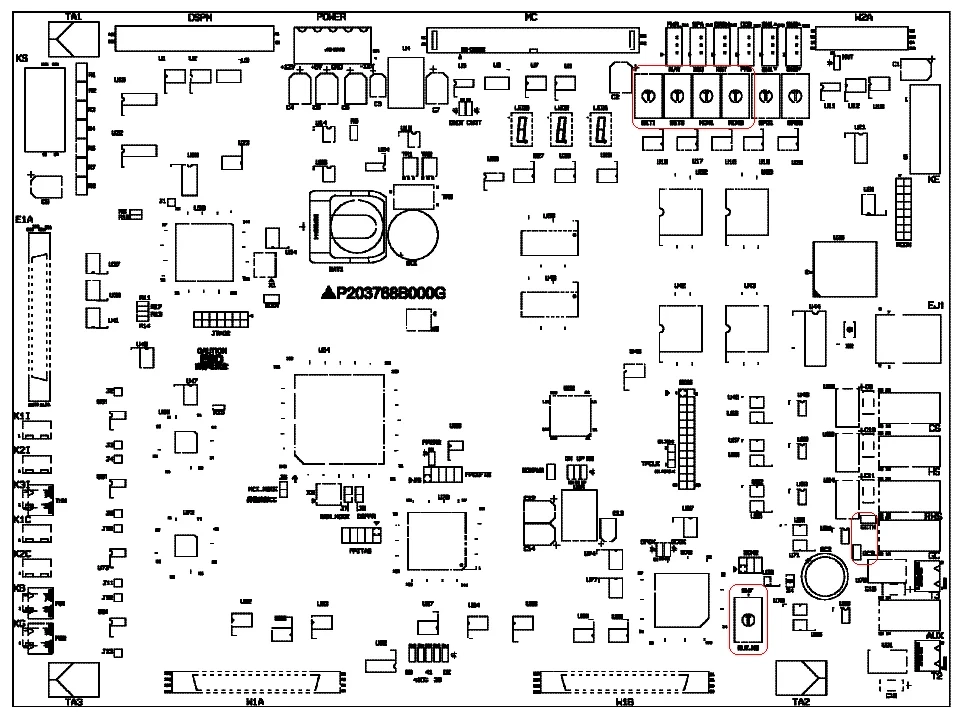
1.1 Operating Mode Configuration
| Function State | MON0 | MON1 | SET0 | SET1 |
|---|---|---|---|---|
| Normal Operation | 8 | 0 | 8 | 0 |
| Debug/Service | Follow debugging manual |
1.2 Communication Configuration (Jumper Rules)
| elevator Type | GCTL | GCTH | ELE.NO (Group Control) |
|---|---|---|---|
| Single Elevator | Not jumpered | Not jumpered | - |
| PArallel/Group | ● (Jumpered) | ● (Jumpered) | 1~4 (for #F~#I elevators) |
2. Car Top Station (Item 231) Settings
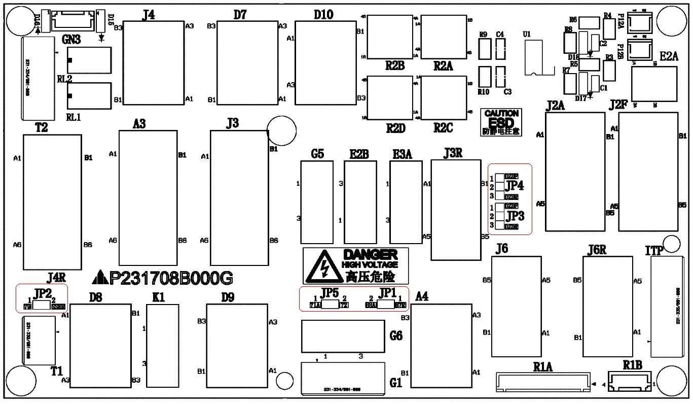
2.1 Door Control Board (Model: P231709B000)
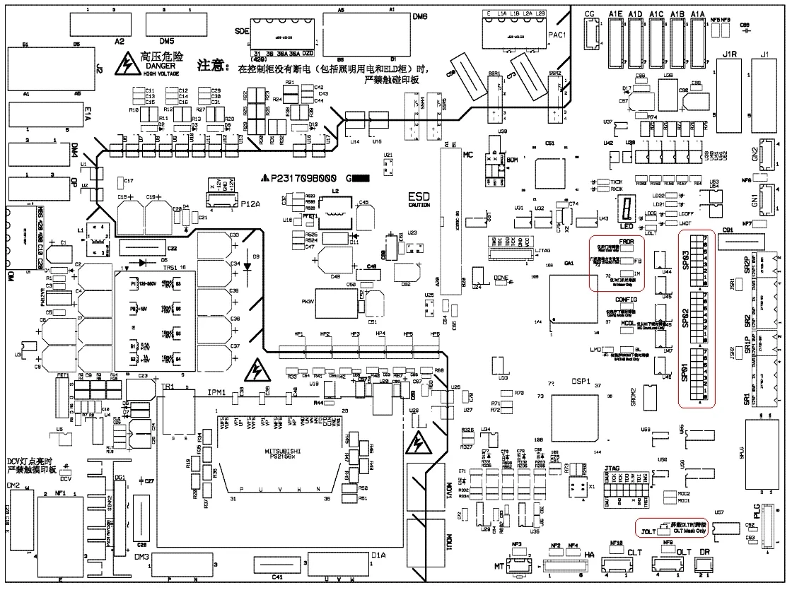
2.2 Basic Jumper Settings
| Function | Jumper | Configuration Rule |
|---|---|---|
| OLT Signal Disable | JOLT | Jumper if only CLT/OLT is installed |
| Front/Rear Door | FRDR | Jumper for rear doors |
| Motor Type Selection | IM | Jumper for asynchronous motors (IM) |
2.3 Motor Direction & Parameters
| Door Motor Model | Motor Type | FB Jumper |
|---|---|---|
| LV1-2SR/LV2-2SR | Asynchronous | ● |
| LV1-2SL | Synchronous | ● |
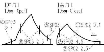
2.4 SP01-03 Jumper Functions
| Jumper Group | Function | Configuration Rule |
|---|---|---|
| SP01-0,1 | Control Mode | Set per door motor model |
| SP01-2,3 | DLD Sensitivity | ●● (Standard) / ●○ (Low) |
| SP01-4,5 | JJ Size | Follow contract parameters |
| SP02-6 | Motor Type (PM only) | Jumper if TYP=0 |
2.5 Jumper settings for JP1~JP5
| JP1 | JP2 | JP3 | JP4 | JP5 | |
| 1D1G | 1-2 | 1-2 | X | X | 1-2 |
| 1D2G/2D2G | X | X | 2-3 | 2-3 | 1-2 |
Note: “1-2” means the corresponding jumper pins 1 and 2; “2-3” means the corresponding jumper pins 2 and 3
3. Car Operating Panel (Item 235) Settings
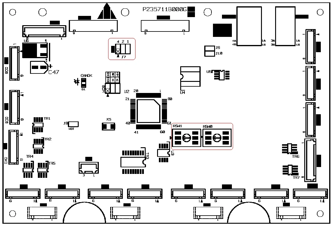
3.1 Button Board (Model: P235711B000)
3.2 Button Layout Configuration
| Layout Type | Button Count | RSW0 Setting | RSW1 Setting |
|---|---|---|---|
| Vertical | 2-16 | 2-F | 0-1 |
| 17-32 | 1-0 | 1-2 | |
| Horizontal | 2-32 | 0-F | 0 |
3.3 Jumper Configurations (J7/J11)
| Panel Type | J7.1 | J7.2 | J7.4 | J11.1 | J11.2 | J11.4 |
|---|---|---|---|---|---|---|
| Front Main Panel | ● | ● | - | ● | ● | - |
| Rear Main Panel | ● | - | ● | ● | - | ● |
4. Landing Station (Item 280) Settings
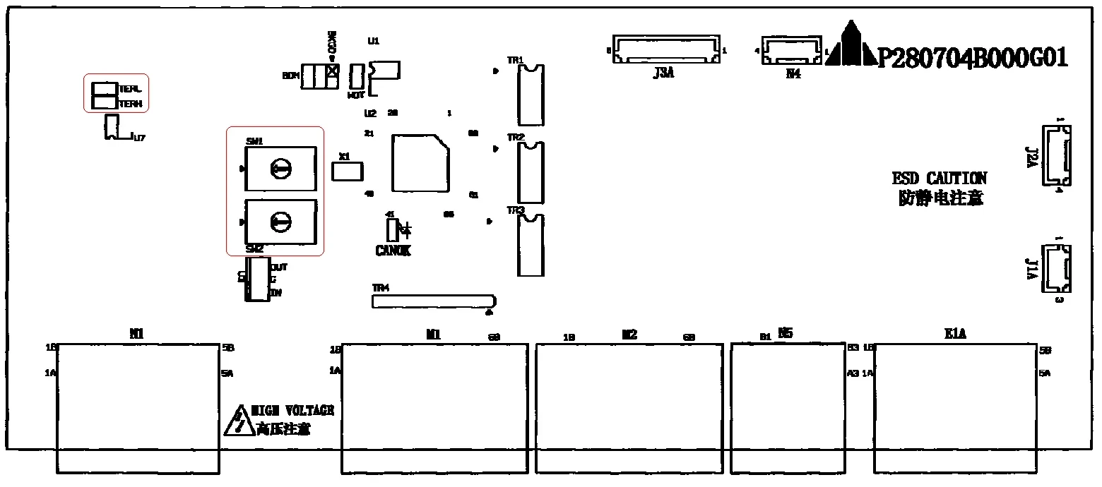
4.1 Landing Board (Model: P280704B000)
4.2 Jumper Settings
| Floor Position | TERH | TERL |
|---|---|---|
| Bottom Floor (No Display) | ● | ● |
| Middle/Top Floors | - | - |
4.3 Floor Button Encoding (SW1/SW2)
| Button Number | SW1 | SW2 | Button Number | SW1 | SW2 |
|---|---|---|---|---|---|
| 1-16 | 1-F | 0 | 33-48 | 1-F | 0-2 |
| 17-32 | 1-F | 1 | 49-64 | 1-F | 1-2 |
5. Landing Call (Item 366) Settings
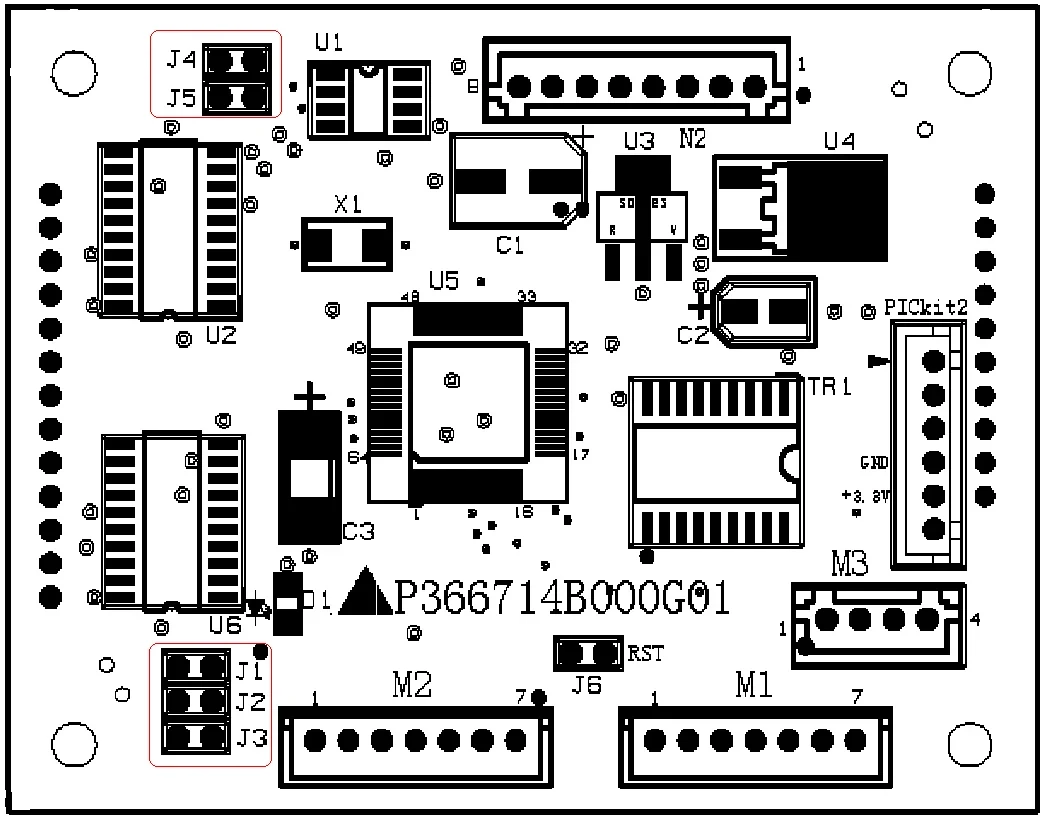
5.1 External Call Board (Models: P366714B000/P366718B000)
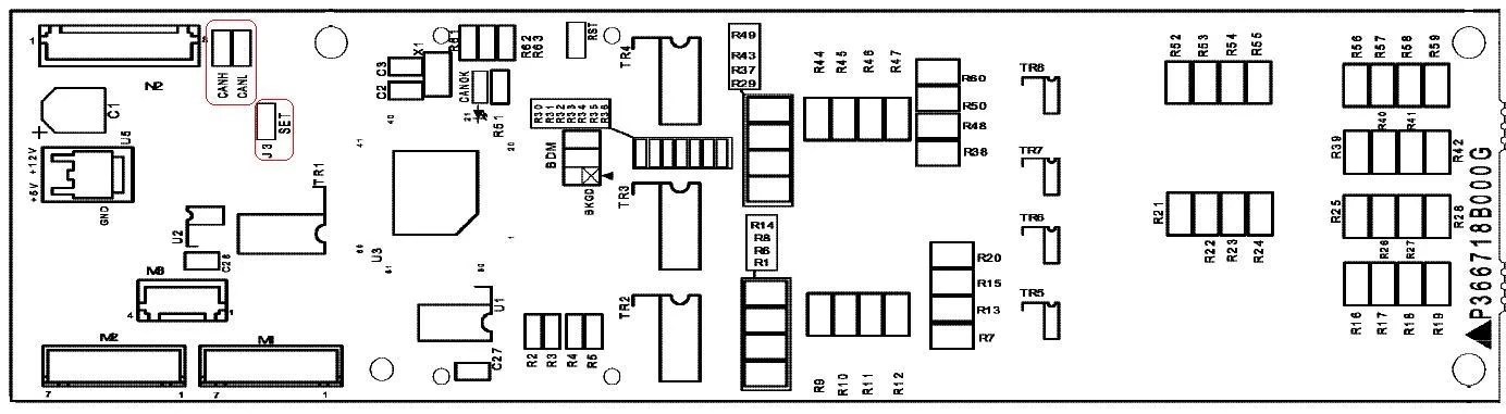
5.2 Jumper Rules
| Function | Jumper | Configuration Rule |
|---|---|---|
| Bottom Floor Comms | CANH/CANL | Always jumpered |
| Floor Setup | SET/J3 | Jumper temporarily during setup |
| Rear Door Config | J2 | Jumper for rear doors |
6. Critical Notes
6.1 Operational Guidelines
-
Safety First: Always disconnect power before jumper adjustments. Use CAT III 1000V insulated tools.
-
Version Control: Revalidate settings after system upgrades using the latest manual (August 2023).
-
Troubleshooting: For error codes "F1" or "E2", prioritize checking loose or misconfigured jumpers.
6.2 Structured Data Suggestion
Technical Support: Visit www.felevator.com for updates or contact certified engineers.
Illustration Notes:
-
Control Cabinet P1 Board: Highlight GCTL/GCTH positions, ELE.NO zones, and MON/SET rotary switches.
-
Door Control SP Jumpers: Color-code sensitivity and motor type zones.
-
Car Button Board: Clearly label J7/J11 jumpers and button layout modes.
-
Landing Board: TERH/TERL positions and SW1/SW2 floor encoding.
-
Landing Call Board: CANH/CANL communication jumpers and floor setup areas.


