
1. SCMAIN Input/Output Configuration
► AS.SCMAIN: Check the debugging circuit diagram and refer to the connectors to find the required inputs/outputs:
– SCMAIN.IN: 6 pairs of inputs (12 pins).
– SCMAIN.OUT: 3 pairs of outputs (6 pins).
| Function | I/O Name | ChAracter | Assigned to PCBA | Installed services |
| AES | KAESBATOK | Required | I2 | AESD |
| KEF | Required | I1 | ||
| KEFE | Required | O1 | ||
| BR2(EN) | JBF-A | Optional | I5 | JBF-A in the control cabinet |
| SUMM | Required | O3 | Service available | |
| RBFF | Required | O2 | ||
| Earthquake | DEB-A | Optional | I6 | Button DEB-A in the control cabinet |
| DM236 | LASZ | Required | O2 | Service available |
| LUET | LUET | Optional | O3 | MR LUET light |
► For specified commissioning services, please refer to the commissioning circuit diagram.
► AS: Set the following switches to ON:
| JH | SIL | SIS |
► Waiting for the startup sequence to complete.
The HMI displays "INS".
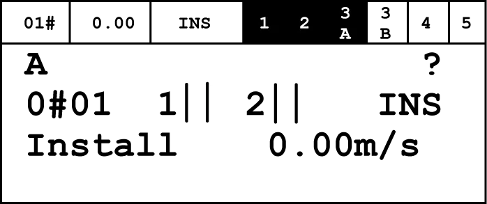
► AS. SCPOW: Sets JRH/JEM to INSPECTION.
- This operation initiates "Service Access" mode, indicated by a flashing "*" in the upper right corner of the HMI.
► AS.HMI: Initiates the input/output configuration process.
HMI: Command → Program I/O function → OK.
- The HMI displays a list of PCBA types with configurable I/O functions.
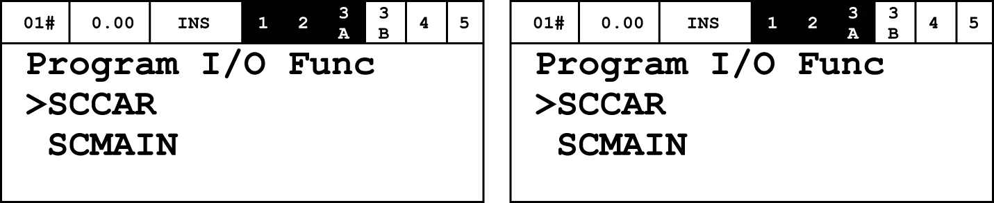
► HMI: List of PCBAs → SCMAIN → OK.
– The HMI displays a list of I/Os that need to be configured. These are identified by the I/O numbers on the connectors: I1 ... I6, O1 ... O3.
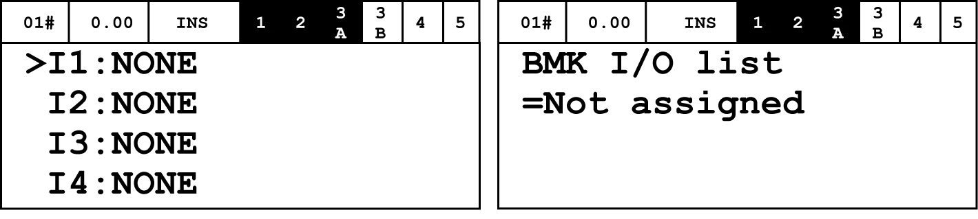
► HMI: I/O List → I/Ox to be programmed → OK.
- The HMI will display the functions currently available for this pin.
► HMI: I/O functions available → Function selected → OK.
- The HMI displays confirmation.
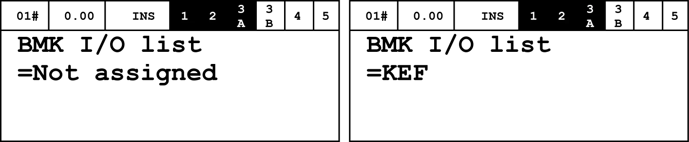
► HMI: The HMI accepts "Success".
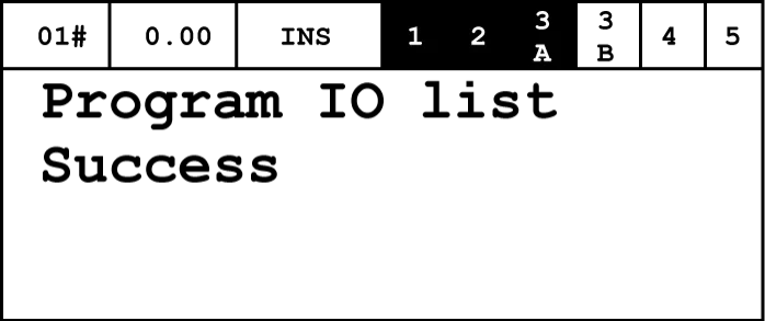
► HMI: Stop using ESC, then select other I/O until all necessary configurations are complete.
► Repeat the configuration process for all other necessary I/Os.
► HMI: Save the I/O configuration.
HMI: Commands → FreezeNodeTr → OK.
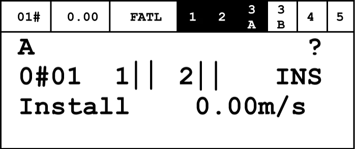
► HMI: Check the results of the completed steps.
The LCD segment in the upper right corner must display " " (empty field) or "!".
2. SCCAR Input/Output Configuration
► Check if there are any inputs or outputs on the SCCAR PCBA that require configuration and if they match the ordered elevator options.
The following table summarizes these I/Os:
| Function | I/O | Character | Assigned to SCCAR | Remark |
| Empty car monitoring | KCL | Required input | I1 | When ordering options |
| Emergency exit monitoring | KNA-I | Required input | I2 | Hong Kong regulations require |
► If there are IOs that need to be configured, follow the steps in the previous chapter, but select SCCAR PCBA.
3. Configure inputs/outputs connected to other nodes
The configuration process is the same for all interface types.
Inputs/Outputs Available:
– Connect switches or indicator lights in LOP, LIP, or LCUX.
– Connect building signals in BIOGIO and CANGIO.
► AS. SCPOW: Set JRH/JEM to INSPECTION.
Prevent elevator operation.
► AS.HMI: Initiate the input/output configuration process.
HMI: Command → Program IO function → OK.
– A list of all PCBA types with configurable I/O can be displayed on the screen.
► HMI: Select the PCBA type for which I/O configuration is required.
– The HMI displays a list of the selected PCBA types.
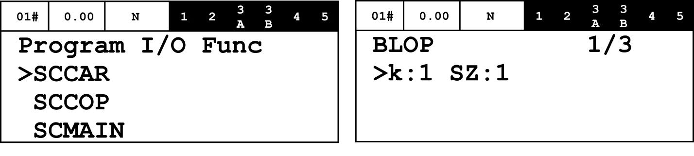
► HMI: Press the OK button:
– In BLOP, BLIN, LCUM, and LCUX PCBA, by its associated floor (k) and entrance side (SZ).
– In BIOGIO, by its software name (E9, EA, or EB).
– In CANGIO, by the location set by its node ID (0...F).
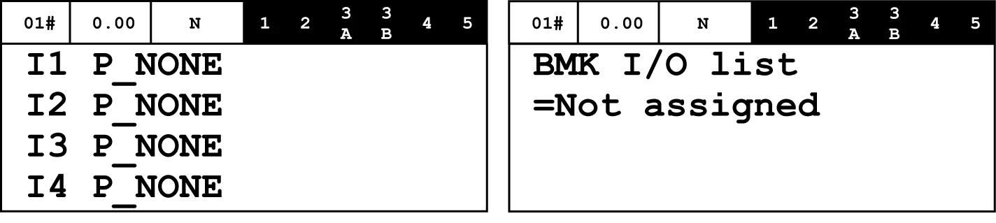
► HMI: Displays a list of I/Os that need to be configured, labeled in order:
– Ix represents input, Ox represents output.
► HMI: Select the I/O to be programmed.
► HMI: Press OK.
– HMI displays the function currently provided to this pin.
► HMI: Select until the function is configured.
► HMI: Press OK to confirm.
► HMI: HMI accepts "Success".
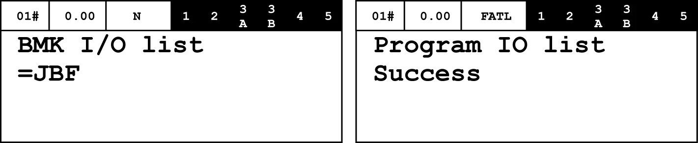
► HMI: Stop using ESC, then select other I/O until all necessary configurations are complete.
► Repeat this process for all other PCBAs.
► HMI: Save the I/O configuration.
HMI: Commands → FreezeNodeTr → OK.
► HMI: Check the results of the completed steps.
The top-left LCD segment must display either an empty field or an exclamation mark (!).
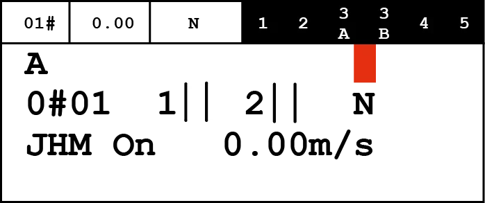
► AS. SCPOW: Set JRH/JEM to NORMAL.
- Elevator resumes normal operation.


