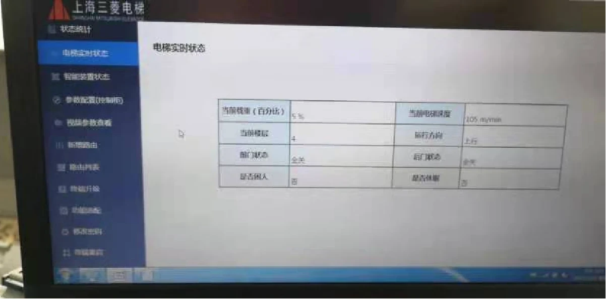
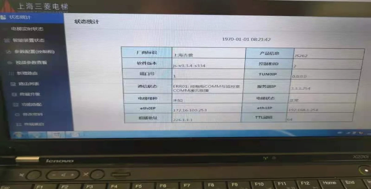
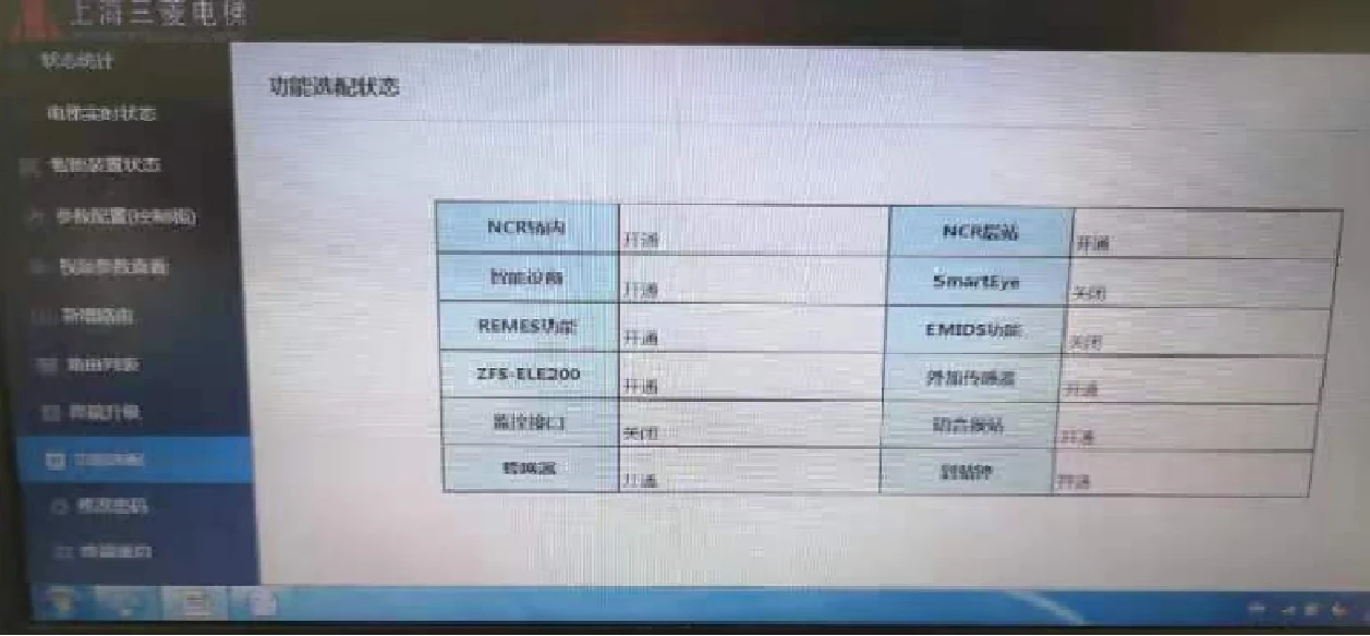
1. SoftwAre Check
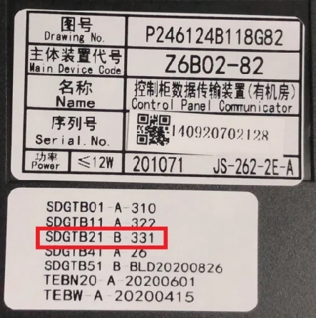
Control cabinet phone and monitoring room phone version, if the version is too low, please upgrade the program.
Monitoring room phone: pkg_js263_cpu_v3.2.4 and above
Control cabinet phone: pkg_js262_cpu_v3.3.5 and above
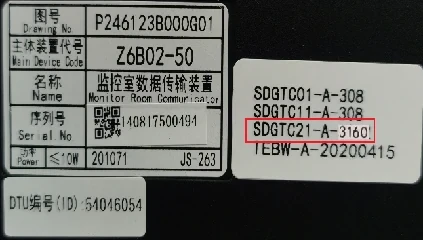
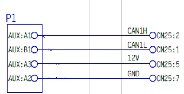
2. Check the line from the phone in the machine room to the P1 board
2.1 Domestic elevator: CN25-P1 board AUX for machine room telephone
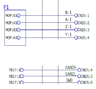
2.2 Introducing VFGLC, VFGH (ELENESSA, NEXWAY-S, etc.):
Machine room phone CN26 to P1 board MOP
Machine room phone CN25 to P1 board PD17
3.Call function check
The telephones in each elevator room and the monitoring room need to be able to communicate normally.
4.Function switch setting
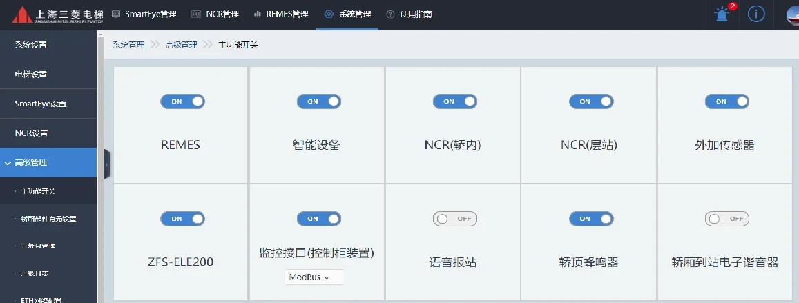
Log in to the monitoring room device WEB page, access the "System Management> Advanced Management> Main Function Switch" interface, open the monitoring interface (control cabinet device), and select the communication protocol (RS485 or MODBUS)
5.BA signal output port wiring
When the user uses the BA interface function, the RS485_1 interface of the control cabinet device CN26 is connected in the form of 485 bus.
The pin position and signal definition of RS485_1 in CN26 are shown in the table:
| Connector Name | Pin Number | Signal name | Output signal | Interface Function Description |
| CN26 | 14 | GND | GND | MODBUS Interface/Dedicated 485 interface |
| 15 | 485-1_B | DATA- | ||
| 16 | 485-1_A | DATA+ |
6.Application restrictions
(1)Imported elevators produced by Mitsubishi Electric Corporation cannot cope with it.
(2)RS-485 serial communication recommends the use of unshielded twisted pair cables, but it must be a bus topology, and the wiring work must be carried out by the weak current party designated by the customer.
(31)The maximum bus length is 1200 meters when the communication rate is 9600bps.
(41)The number of DigTel-II BA interfaces on the same bus shall not exceed 253.
(51)The polling interval for the same DigTel-II BA interface should be greater than 100ms.
7.Functional simulation test
(1)When the weak current company cannot collect the BA signal, or other special conditions are not met, the 485 simulation device can be used for testing.
(2)Hardware preparation: 485 simulation device, USB to RS232 device
(3)Software preparation: Modscan32
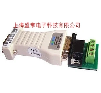
(4)Hardware connection: Connect the USB to RS232 device to the USB port of the debugging computer, install the driver, set the serial port to com1, and connect the 485 analog device to the RS232 port.
(5)485 analog device DATA+ connects to the 16th pin DATA+ of the control cabinet telephone CN26; DATA- connects to the 15th pin DATA- of the control cabinet telephone CN26.
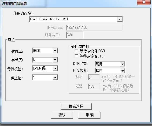
(6)Double-click ModScan32.exe to open the serial port debugging tool, select Connection Settings -> Connection, and set it according to the figure below.
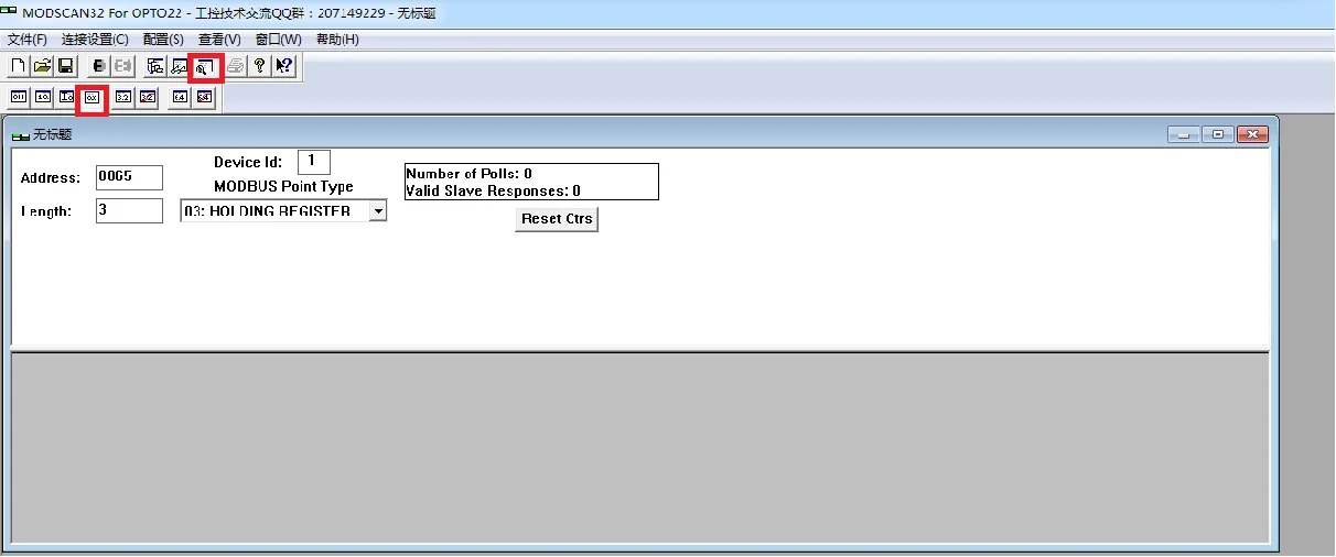
(7)Click on the picture below
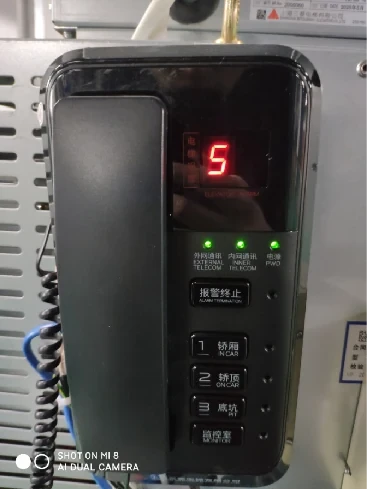
(8)On the control cabinet device/ETP device side, press and hold the "Alarm Stop" key on the keyboard for more than 3 seconds, and the digital tube of the control cabinet device will flash the port number of the device. The port number is displayed in decimal.
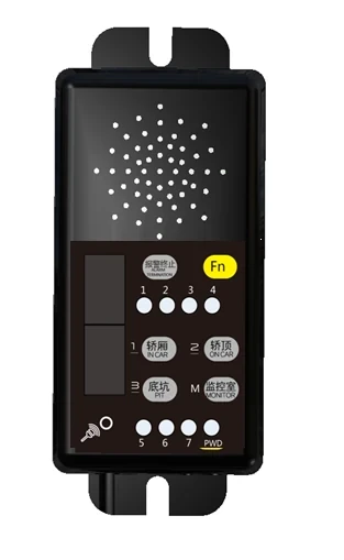
(9)Set Address to 0065, Length to 3, and Modbus point type to 03.
(10)Device ID is set to the port number of the telephone device in the computer room (decimal is fine)
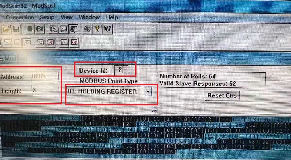
(11)Click the "Connect" button, the computer will send data to the room phone, and the room phone will reply with data.
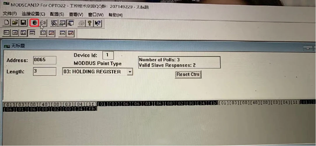
(12)Normal return data packet (BAS←DigTel-II BA interface)
(13)01 (port number, changes according to actual situation) 03 06 XX XX XX XX XX XX CRC (low byte) CRC (high byte)
(14)Among them, the 6 0xXX are the high byte and low byte data of the register with register address 0x40~0x42, not all of them are 00.

(15)Normal response data
8.Check the functions and elevator status via the machine room phone
Software preparation, if the BA signal reply is 00, check the following:
(1) Install the browser (Google or Firefox) on the computer
(2) Connect the computer network cable to the LAN1 of the control cabinet phone
(3) Set the computer IP to: 172.16.100.1
(4) Open the website: 172.16.100.253
(5) Enter the login interface
Username: admin
Password: 200245
(6) Log in